A Brief History of High Railway Bridges
Railroad Bridge Types
Railroad bridges are usually made of either stone, concrete, steel or timber. In North America, stone and concrete arches were rarely used for very high railroad bridge construction due to the difficulty of having to build tall centerings which are large, temporary timber supports curved in the shape of the stone or concrete arch that will be built upon it. Nearly all of the high North American railroad bridges shown within this web site were built of either steel or timber. In Europe and China, timber was almost never used but concrete and stone were quite prevalent. The descriptions below will give you a brief explanation of the most common bridge types. For a more clear and concise understanding of these types of railroad bridges, I highly recommend purchasing the inexpensive and easy to obtain Bridge & Trestle Handbook by Paul Mallery. Just below, you can also download three great turn of the century bridge books that have a lot of railway bridge information: J.A.L. Waddell’s Bridge Engineering, H. G. Tyrrell’s History of Bridge Engineering and for timber bridges, Wolcott Foster’s A Treatise on Wooden Trestle Bridges.
Bridge Book Downloads
- Waddell - Bridge Engineering (~350MB)
- Tyrrell - History of Bridge Engineering (~150MB)
- A Treatise on Wooden Trestle Bridges, 3rd Edition (~80MB)
- File:Truss HAER Poster .pdf
Truss Bridge Triumphs
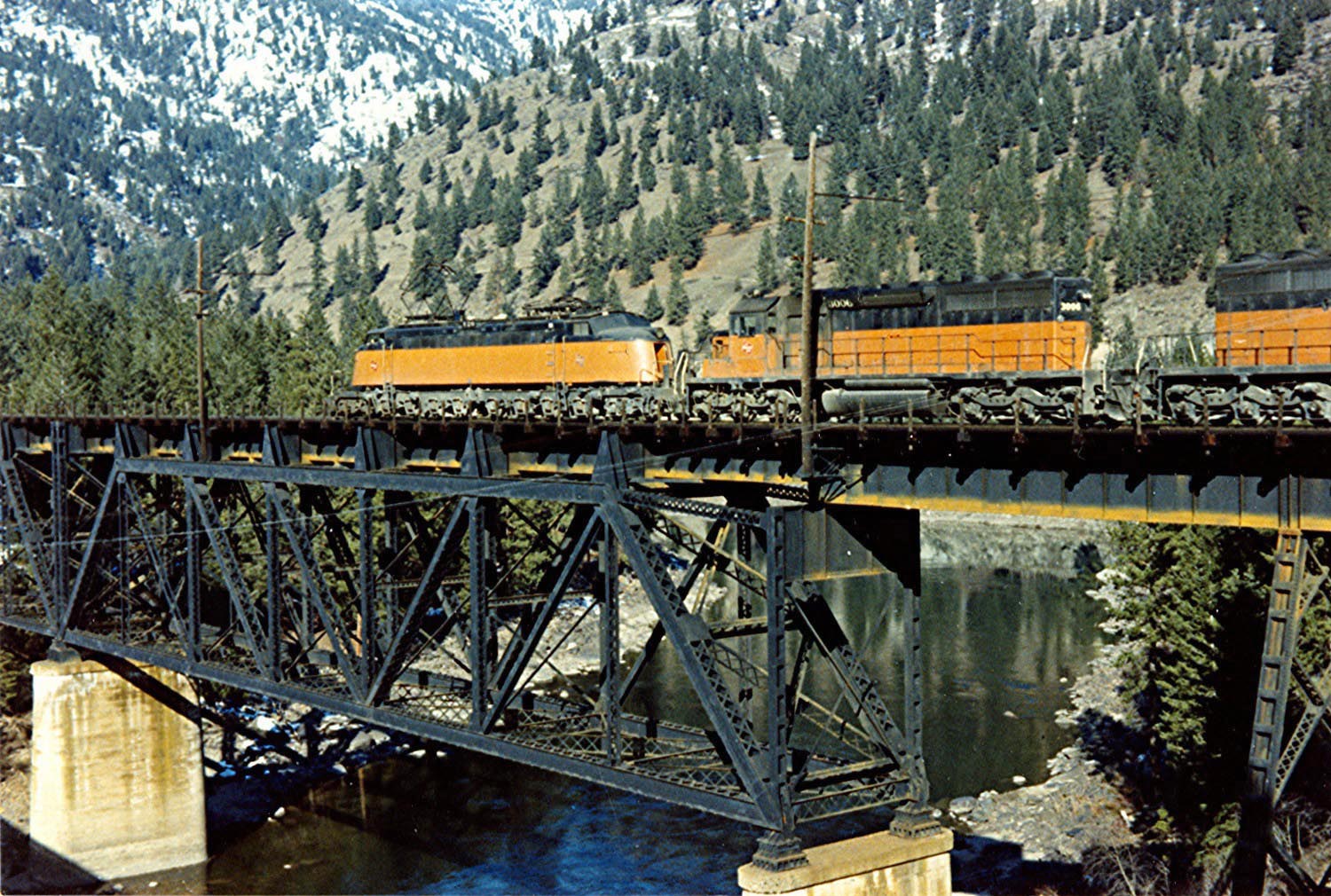
Of the numerous types of large bridges found on railroads around the world, the most common form is probably the simple truss. The basis concept behind all truss bridges is a distribution of the weight across a series of steel triangulated members that are either in compression or tension. To become acquainted with these truss types, I recommend downloading the HAER (Historic American Engineering Record) page above.
Starting in the 1840s, early railroad builders began to use a variety of wrought iron truss forms that were introduced and patented by their designers as the best and most economical way to safely carry the “iron horse” across gaps in the terrain. Named after their inventors, two of the earliest design patents were for the Bollman and Fink truss. Both of these trusses were adequate for the early locomotives that were slow moving and light but became impractical by the late 1800s. The famous bridge engineer J.A.L. Waddell described them best in his 1916 book on bridge engineering, “The Fink and Bollman truss are so eminently lacking in rigidity that the vibrations induced in them by trains passing at high speed are truly alarming. Not only has their construction been entirely abandoned for many years, but most of the old railroad bridges of these types have been removed and replaced by better structures.”
Other truss types from the 1800s that came and went included the Lenticular, Whipple, Kellogg, Pegram and Schwedler. The Pratt, Petit and Warren are among the few that are still in use today. Variations on the Warren have succeeded from the simplicity of the form which is a series of simple triangles. The Warren also benefited from the switch from pin connections to rivets which eliminated eye bars and other tension-only members that allowed the bridge to shake and loosen up over time. These older, more complicated forms also suffered from being multiple-system trusses with additional secondary stresses that created distortion and deflection problems. The forces within the simpler, single-cancellation trusses not only made for a stiffer bridge but an even easier one to manufacture, construct and maintain. Among timber trusses, the Howe became the dominant style and is explained in more detail below. For a better explanation of all of these trusses and their advantages and disadvantages, go to the download above for J.A.L. Waddell’s excellent 1916 book, Bridge Engineering and begin reading Chapter XXII on page 546.
Colossal Cantilevers
As river crossings became wider and deeper and spans became longer, railroad engineers began to look beyond the simple truss bridge as a solution. It came in the form of the cantilever. Instead of using two piers as end points to rest the structure on, the mass of the bridge is built directly over the center of each of the piers and then outward on both sides. The main span of the bridge structure is formed, in effect, from two separate bridges that meet in the middle. The massive weight of these two “arms” that extend out over the river are countered by two separate anchor “arms” that connect to another pier on either shore. To extend the length of the main span, a separate truss is usually suspended between the two river arms. The addition of this central “third” bridge also allows a cantilever bridge to span longer distances than a conventional truss. The extra weight of the central span pushing down on the river arms is countered by the shore arms that actually pull upward on the shore piers. This ability to transfer the weight of the main span to the shore arms was also a major advantage during construction since there was no need for false work over the deepest parts of the river. Truss bridges always need false work until the span is completely finished.
The first major cantilever bridge in the United States was the 1877 built High Bridge over the Kentucky River West of Lexington, Kentucky. With 3 equal spans of 375 feet (114 meters), the wrought iron structure was also one of the highest bridges in North America, towering 275 feet (84 meters) above a deep gorge. In 1911 an even higher and more substantial steel truss replaced it on the same piers as the 1877 original. Following this success, two other large railroad cantilever bridges were built at Niagara Falls between the U.S. and Canada and across the Fraser River near Cisco in the province of British Columbia, Canada. Both were designed by C.C. Schneider though only the Cisco bridge survives, albeit in a different location on Vancouver Island where it was rebuilt in 1912.
Another big cantilever project that came about in the 1870s was for a rail bridge across the deep channels of the Firth of Forth near Edinburgh, Scotland. The mile and a half (2.5 km) structure would have to have not one, but two massive spans of approximately 1,700 feet (520 meters). Approval was first granted to engineer Thomas Bouch for a giant double span suspension bridge but was halted when his previous bridge over the Tay collapsed in a powerful storm in 1879, killing more than 75 people. When the project resumed, momentum gathered behind a monstrous double cantilever bridge design by Sir John Fowler and Sir Benjamin Baker. The unique structure would have over-sized, tubular shaped members - 12 feet (3.5 meters) across - to resist even the strongest gale force winds. When the groundbreaking bridge opened in 1890, it took the record away from the Brooklyn bridge as the new world’s longest span bridge - a claim it would hold for more than 25 years. The success of the huge red bridge, with its signature double bow tie profile, forever cemented the status of the cantilever bridge as the best choice for long span railroad bridges.
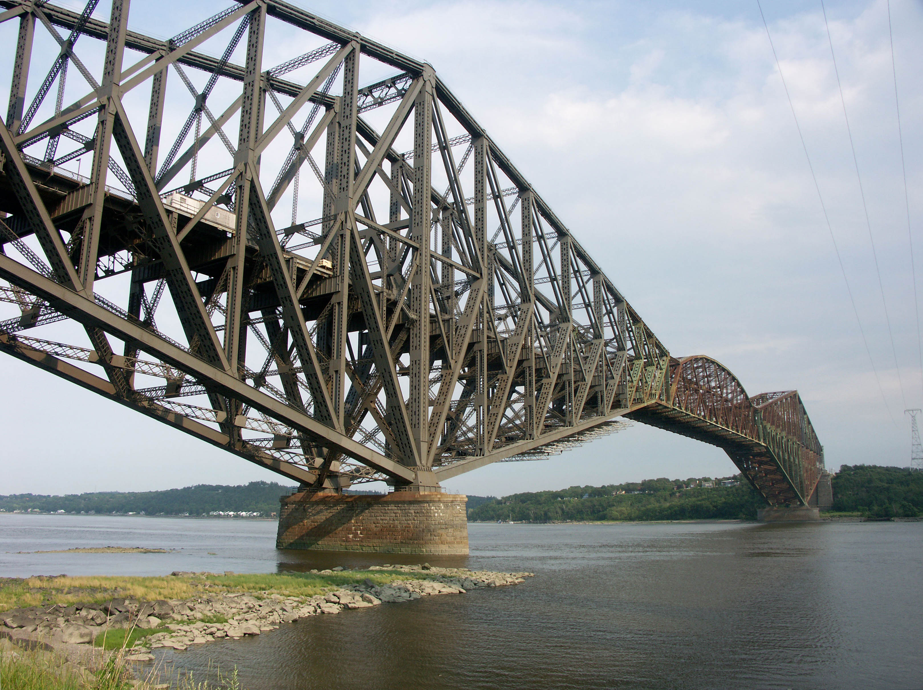
The era of the long span cantilever bridge culminated in 1917 with the building of the Canadian Quebec bridge across the St. Lawrence river. With a main span of 1,800 feet (550 meters), it became the second and last time in history that a cantilever bridge would have the world’s longest bridge span. But unlike the overbuilt design of the Forth bridge, the original plan by engineer Theodore Cooper had truss members that were not thick enough to adequately handle the compressive loads of the massive arms that were rising above them and on August 29, 1907, the nearly completed south end of the bridge completely collapsed, killing 75 workmen. A second structure was built with the same span configuration as the first bridge with a design that used much stronger members. Like the Forth bridge, the Quebec bridge became world famous. It also had a unique look with its double diamond profile and repetitive K-bracing.
While no other railroad truss or cantilever bridge has been built with a span as large as the Quebec bridge, several other large scale cantilever crossings were constructed in the years following including the Beaver bridge, located 20 miles (32km) north of Pittsburgh, Pennsylvania and completed in 1910 by the Pittsburgh and Lake Erie railroad with a span of 767 feet (234 meters) and in New Orleans, Louisiana, the 1935 built Huey P. Long bridge with a main span of 790 feet (241 meters).
Towering Trestles
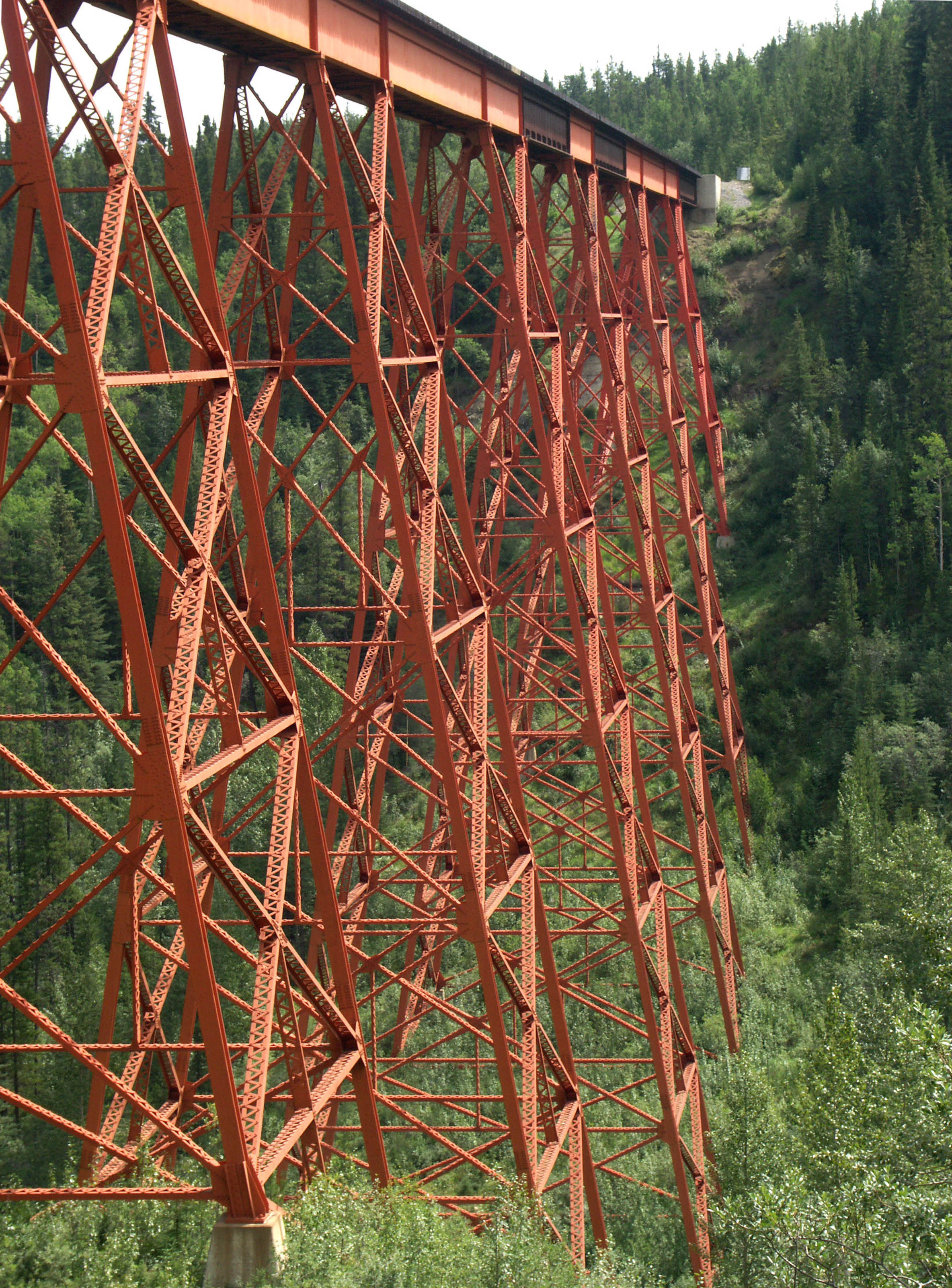
Unlike the longer spans of the truss and cantilever that were practical for large river crossings, railroad designers developed the steel or timber trestle to cross wide valleys and steep ravines. The term “bridge” usually refers to a structure that contains a long central span flanked on either side by approach spans of considerably shorter length. A viaduct or trestle is a bridge structure with no main central span but a series of smaller spans of similar or equal length. Viaducts generally have longer spans than trestles and derive their look from the repetitive nature of the evenly spaced piers that support them. While both railroad and road bridges can be considered a viaduct, only a rail bridge can be called a trestle. Steel trestles consist of a series of short and long plate girders that alternate over a row of box-shaped towers that taper outward from the deck to the ground. Trestles derive their strength from these four-legged towers whose foundation spread can sometimes be as wide as 100 feet (30 meters).
Referred to as the “tower span”, the shorter plate girders at the top of each tower can range in length from 25 feet (8 meters) to as much as 50 feet (15 meters). The monstrous Lethbridge Viaduct in British Columbia, Canada is a rare exception with tower spans of 67 feet (20 meters). The intermediate spans that cross between the towers are usually longer, ranging from 50 to 100 feet (15 to 31 meters). Many trestles have a deck or through truss for the longer spans that are sometimes required to cross directly over the river or stream. Despite their business-as-usual look, trestle aesthetics can come into play if the engineer chooses to use only diagonal struts which look less jumbled and more pleasing to the eye than if horizontal or vertical struts are added to brace them to the main posts. Depending on your point of view, the choice of whether to keep the girder a uniform depth or vary them based on the span length can also add or detract to the look of the structure.
Timber Titans
If the first use of a timber bridge began when a log was placed across a stream, it was the development of the railroad from the early 1830s onward that really pushed engineers to create the towering wood trestles featured in this web site. Timber trestles were one of the few railroad bridge forms that did not develop in Europe but in the United States and Canada where cheap lumber was widespread and readily available in nearby forests. The Pacific Northwest of the U.S. and the province of British Columbia, Canada became the central region for hundreds of logging railroads whose bridges were almost all made of timber Howe trusses and trestles.
Timber trestles generally come in two forms. The first and most common is the pile trestle which consists of bents spaced 12 to 16 feet (4 to 5 meters) apart. Each bent consists of 3 to 5 round timber poles that are pounded straight into the ground by a pile driver. The outside posts are usually battered, angling outward for stability. During construction, the top of the uneven posts are cut to the proper level for a cap which in turn supports the stringers and planks that hold the rail. Taller pile trestles contain diagonal “X” bracing across one or both sides of the bent and also between bents.
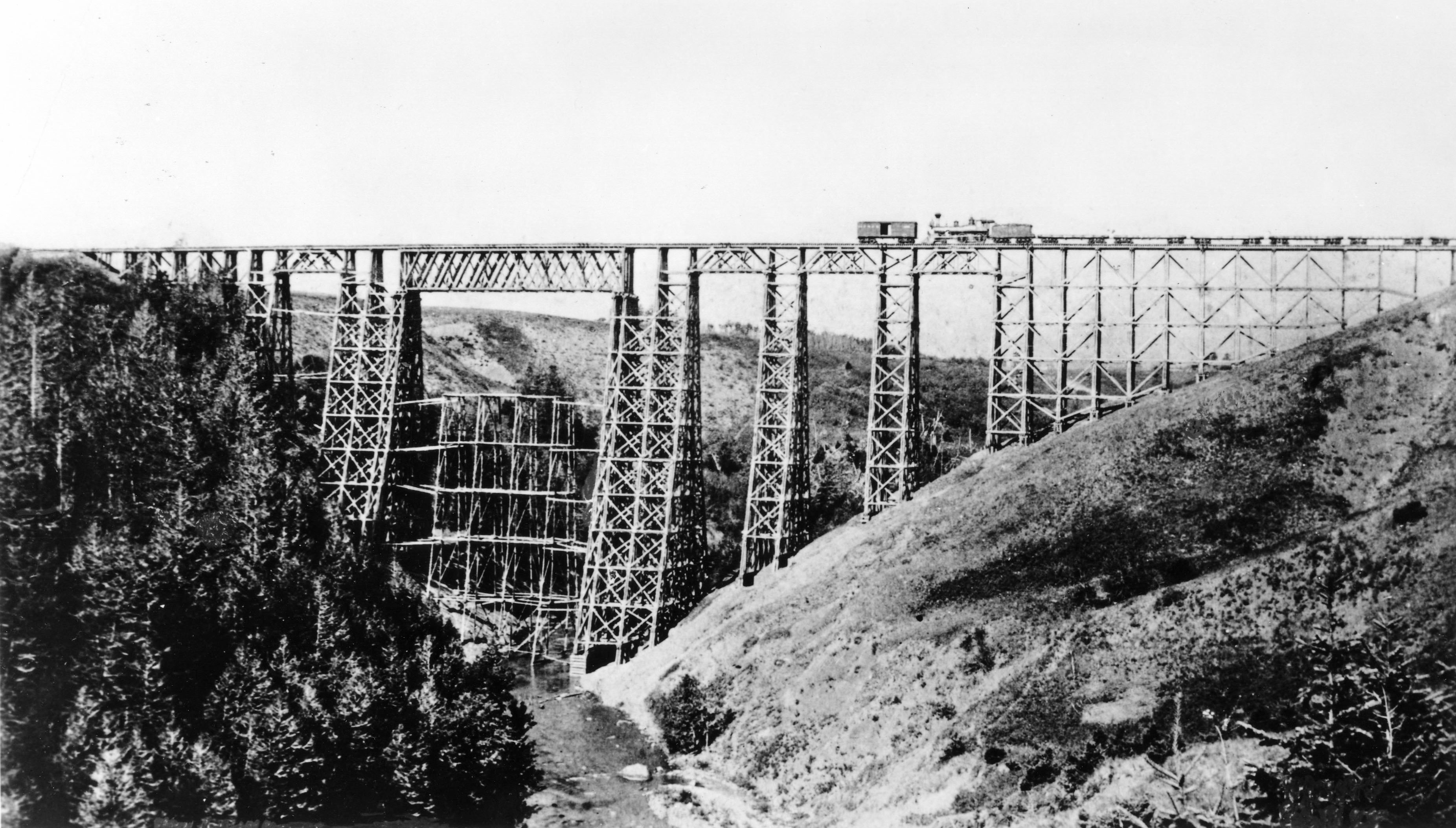
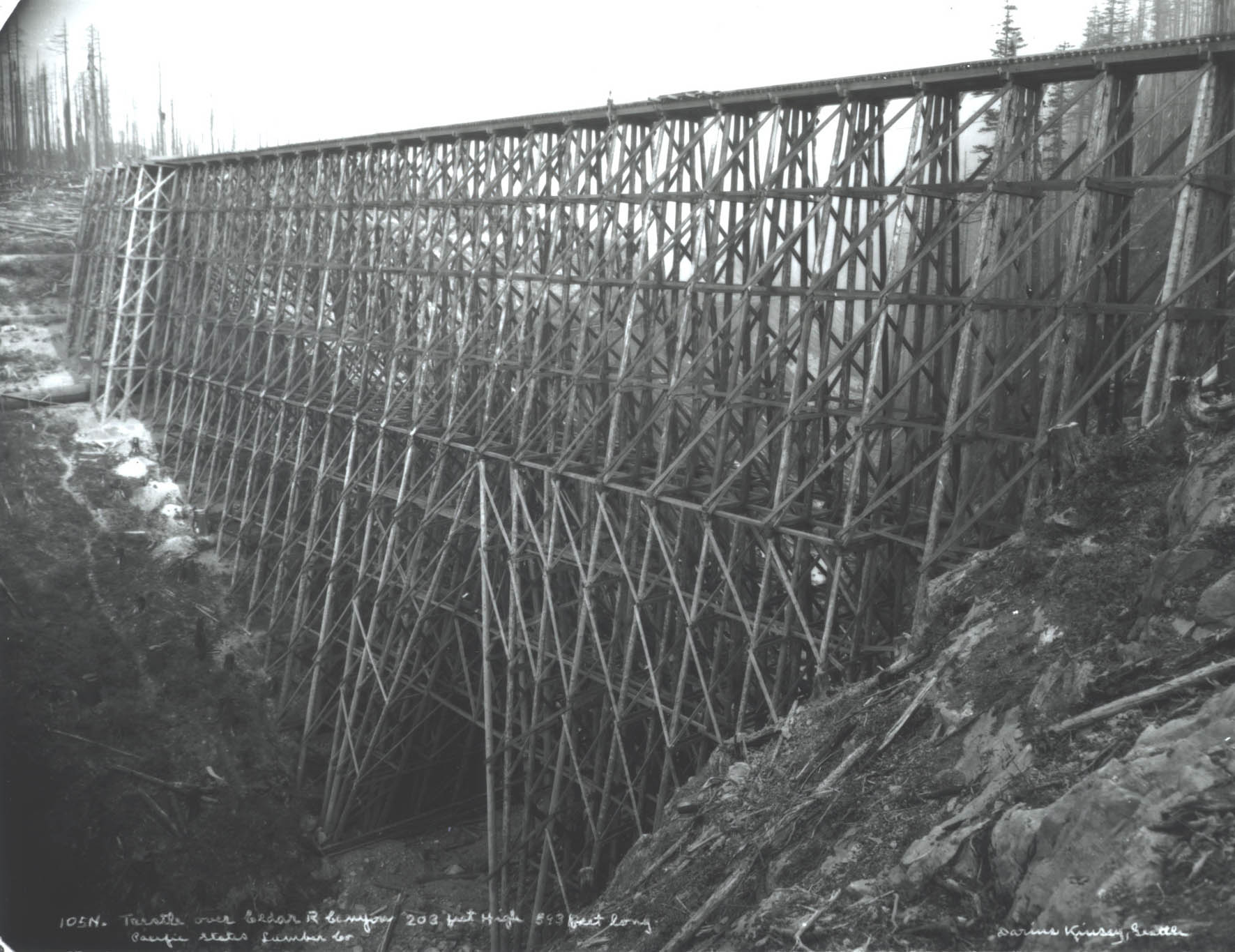
For higher timber trestles, the framed bent is used. Unlike pile bents, frame bents usually use square timbers and rest on mud sills or sub sills that act as a foundation. Frame bents are built in a series of “stories” that are usually between 10 and 50 feet (3 and 16 meters) high. For extremely high trestles, each section of the bent is built flat on the ground as a single or double story and then lifted across the valley on an aerial high line where it is lowered onto the continually rising structure before the process is then repeated for the next level.
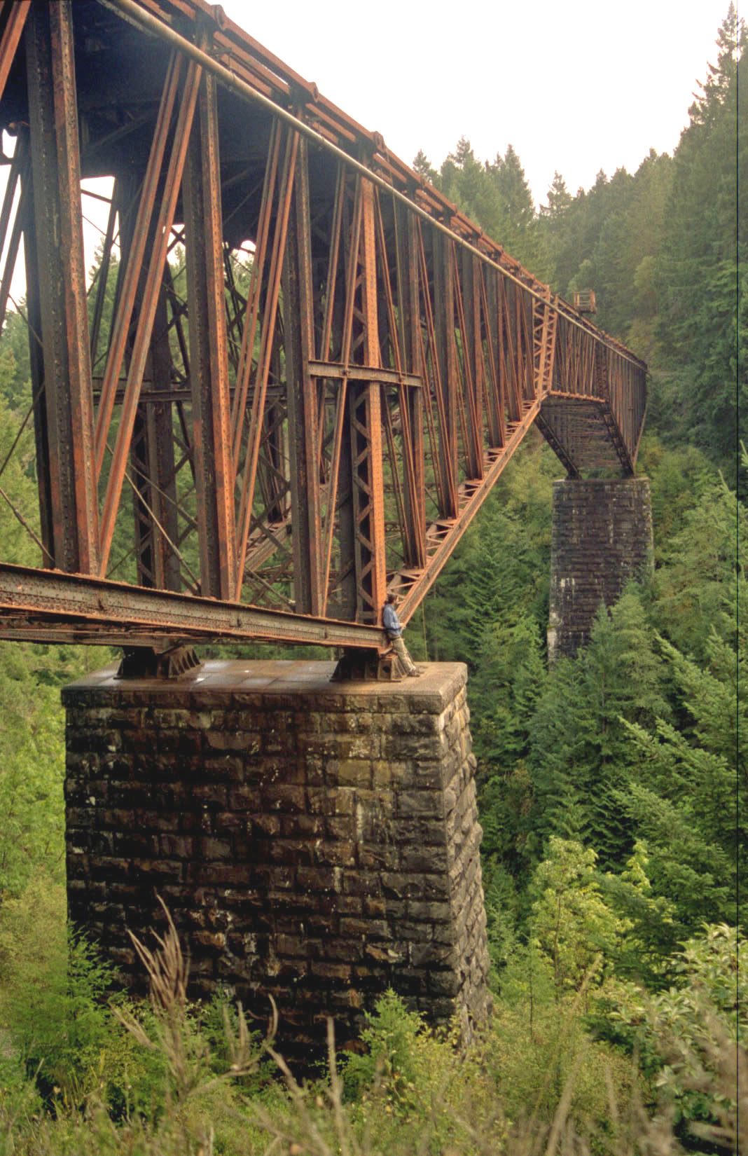
None of the dozen or so highest timber bridges of all time exist anymore. Nearly half of these 200 foot (61 meter) high monsters were built for logging railroads in the U.S. state of Washington and on Vancouver Island in British Columbia, Canada. For the lumber industry, rail lines were usually little more than a web of dead end tracks blanketed across the contour lines of a forested mountainside. Once the terrain was logged out, the tracks were abandoned. Since lumber was easy to find and abundant, it could quickly be cut on-site into tall piles or bents. With nothing built to last, construction standards were often low. Expensive bridges, especially those made of steel, were avoided.
Early timber bridges had their drawbacks. Untreated lumber only lasted about 20 years and locomotives could easily cause the wood to catch fire. Collapses - rare today - were a regular occurrence on logging railroads and there are numerous accounts of train crews that regularly hopped off their slow moving locomotive as it approached a high, untrustworthy trestle, allowing it to cross before they would then run across the bridge and jump back on. On main lines that carried passengers and freight, tall timber bridges reduced efficiency as trains had to cross them at slower speeds. Initially they were a quick way to get the route open but once established, the owners usually had them replaced with steel bridges or filled. The Great Northern, Milwaukee Road and Canadian Pacific railroads all originally crossed the Rocky Mountains on several towering timber bridges that were replaced a short time later with steel.
Of the hundreds of logging railroads that once existed in the Pacific Northwest, there are just two still in operation - Canfor’s (Canadian Forest Products) Englewood Logging Railway on the north end of Vancouver Island and the Simpson Logging railroad of Shelton, Washington on the Olympic peninsula. Not surprisingly, these two successful holdouts have some of the most spectacular bridges ever constructed for a logging railroad including the two highest steel arch bridges ever built for a railroad in the United States. Today, timber trestles are still common on railroad bridges throughout North America but heights of more than 100 feet (31 meters) are rare.
As easy and simple as it was to construct timber trestles over small creeks and streams, the longer spans required to cross over wide rivers required a whole new type of bridge which came in the form of the Howe truss. As explained previously, the development of the iron and steel truss bridge went through a lot of growing pains throughout the 1800s with dozens of variations developed by several prominent bridge engineers. By the late 1800s, when the dust had finally settled it was evident that the Howe truss would become the long span timber truss bridge of choice with few railroads using any other type. The secret to the Howe’s popularity was the use of adjustable iron rods placed vertically between the top and bottom chords. They kept the timber members in compression and allowed maintenance crews to tighten the entire structure when connections expanded and became loose, reducing the tendency of the bridge to flex when trains passed over it. After 1900, timber Howe’s were quickly being replaced by steel trusses due to the ever increasing weight of newer locomotives.
The only other timber truss type that had any longevity was the Lattice or Town truss which gained its strength from a tight web of overlapping diagonal members. Commonly used for covered road bridges throughout the 1800s, the few that were used on railroads were in France and Italy where they were made of iron or steel.
Acrobatic Arches
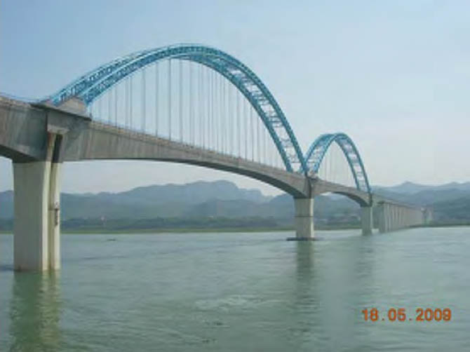
The simple arch bridge. Not only is it the most beautiful and spectacular of all railroad bridge types but it is also the most perfect form for handling the heavy load of a train since the materials in the bridge are always in compression. Arches are shaped into some form of either a semicircle or a segmental. If the arch is made of steel, hinges are often located at the two springing points to relieve temperature related expansion and contraction stresses. A three hinged arch contains yet a third expansion pin at the crown. The open spaces between the arch and the deck are called spandrels and are a standard design element on any large steel or concrete arch. Stone or masonry arches are almost always semicircular and rarely have open spandrels. The arch rib on a steel span can be solid or braced, with diagonal supports extending to the deck in place of ordinary spandrels. Less common on railroad bridges but still quite popular is the tied arch where the rail or road deck travels through the arch, suspended on beams or cables underneath. Forces that normally thrust outwards at the base or skew backs of the arch are held together or “tied” by the deck, allowing the weight of the structure to only push downward on the piers in a vertical direction.
When the earliest railroads came on the scene in the 1830s, bridge engineers had yet to perfect the arch bridge with either timber or steel, so it was only natural that the stone or masonry arch bridge carried the first locomotives over the rivers and streams of Europe and North America. The Carrollton Viaduct on the Baltimore and Ohio and the Starrucca Viaduct on the New York & Erie were two of the largest North American stone bridges of that era. By the 1870s, longer arch spans of steel had risen over the Rhine in Germany at Coblenz and Duisburg while in the U.S., James Eads made the first crossing of the Mississippi with his triple span triumph at St. Louis. Despite this proof that the arch form was a viable alternative to the incredibly popular truss, railroads in North America continued their ongoing love affair with the truss and the cantilever since they had the advantage of higher and wider navigation clearances that were required to cross large rivers like the Ohio and Mississippi.
For wood truss bridges, the use of a timber arch to complement the truss was an additional way to strengthen longer spans and reduce sagging. This combination, called the Burr arch-truss after its inventor Theodore Burr, was more common on covered bridges that carried roads but was also incorporated on many of the early long span railroad bridges. Among deck arch bridges, where the road or railway rides on top of the arch, it is surprising how few of the timber span type were built in North America. Among high bridges, the two most notable examples were the Cascade bridge that once carried the New York and Erie railroad across a 175 foot high (53 meter) gorge north of Lanesboro, Pennsylvania and the Carthage road bridge in Rochester, New York which stood for one year before it collapsed into the Genesee River. These two goliaths are a contrast in how a good arch design must take into account the organic, variable nature of wood.
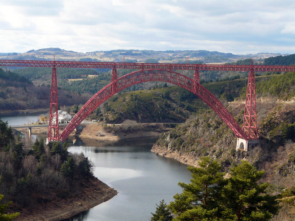
By the late 1800s, the steel arch had become quite popular for long span railway bridges in Europe. Three notable examples being engineer Gustav Eiffel’s Maria Pia and Luiz I bridges in Oporto, Portual and the Garabit Viaduct in St. Flour, France. All 3 held the record for the longest span steel arch bridge. It would not be until 1915, when New York City’s Hellgate bridge opened, that such a large railroad arch bridge would come to North America with its massive steel span of 977 feet (298 meters).
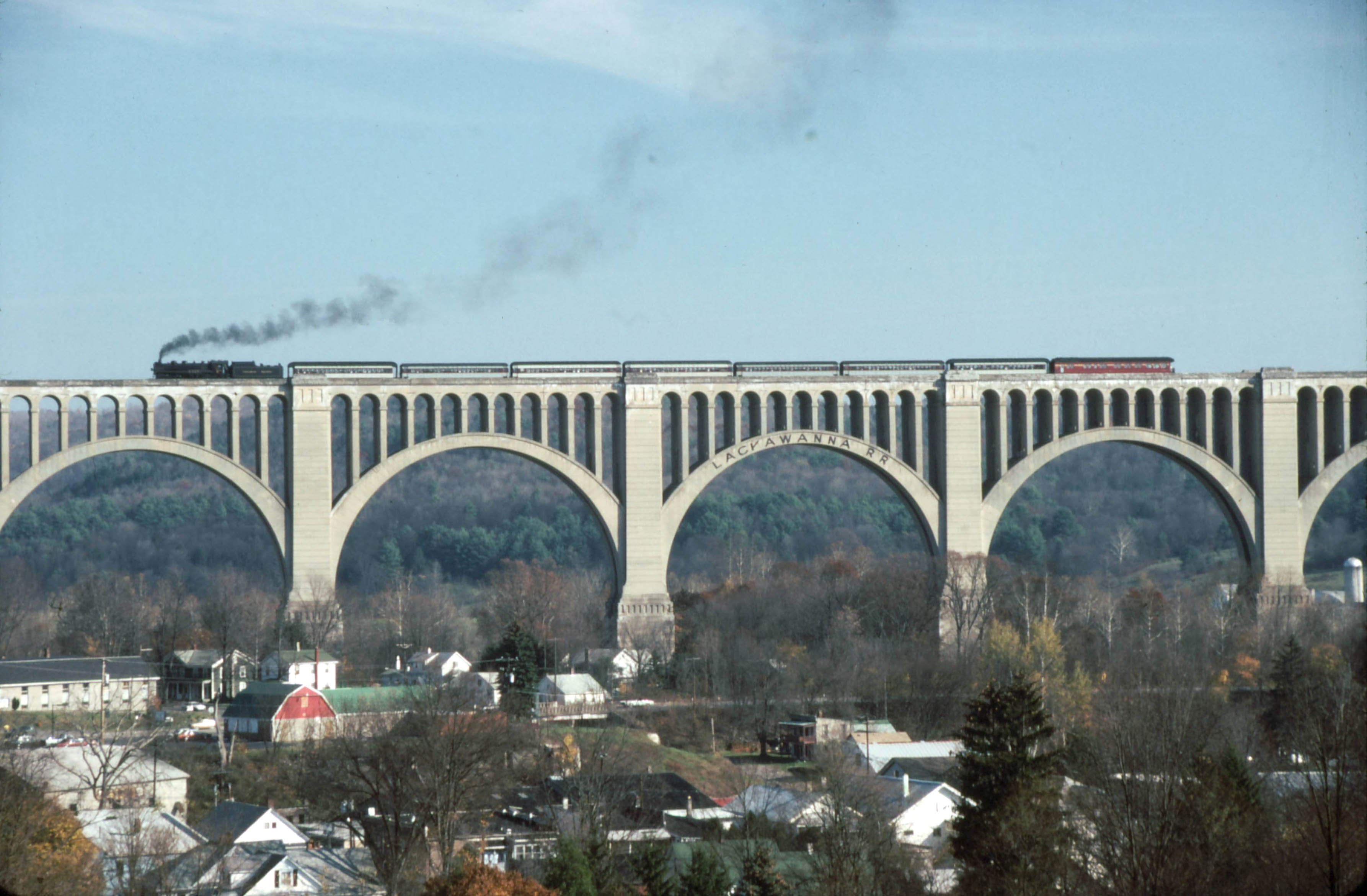
After 1900, concrete had developed to a point where engineers were building larger arches with less mass than their masonry counterparts. Spandrels were airier and more open with slimmer deck supports. The ability to divide the main arch span into separate ribs - once only possible with steel - was now a standard feature of these new concrete creations. In addition to saving a builder both money and materials, concrete also allowed the structure to look “modern” with unusual shapes and curves previously unseen on a bridge. For sheer scale, such railroad bridges reached a zenith in 1915 when the 240 foot (73 meter) high Tunkhannock Viaduct opened in Nicholson, Pennsylvania on the Delaware, Lackawanna & Western railroad as North America’s largest concrete arch bridge ever.
Beam Bridge Beauties
Probably the most common and simple of all bridge types, the beam or girder bridge is often the most overlooked of bridge forms. Largely considered to be boring and unattractive, beam bridges went through an incredible period of advancement after 1950 when France and Germany began to experiment with longer spans made from “prestressing”, a process whereby the concrete girders are compressed before any loads are placed upon them. This is done with steel cables or “tendons” that are threaded through the beam and then tightened or “tensioned” with jacks and anchors. This process reduces the amount of cracking that occurs in more conventional reinforced concrete beams. It also improves aesthetics - thick and bulky spans can be thin and light. Concrete spans that were once limited to around 100 feet (30 meters) in the early 1900s are now more than 1,000 feet (305 meters) in length.
Prior to the modern era of long span beam bridges, steel was the primary material for girder bridges - especially for those built by the railroads. Limited to a length of around 100 feet (30 meters), a railroad beam span is usually made up of two vertical “plates” that run parallel to each other. These girders are strengthened by the addition of a flat cover plate on the top and the bottom. Further rigidity comes from intermediate stiffeners spaced every few feet along the length of each girder. Placed side by side, the two girders are connected to each other by a series of intermediate beams and laterals that look like a Warren truss. Some form of railway decking is then placed on top of this box-shaped beam. For road bridges, the design is nearly the same but with several extra plate girders needed to support the wider deck. If there are clearance issues below the span, the two girders are placed above the level of the track allowing the train to travel between them, hence the name through plate-girder bridge.
Despite the fact that truss and arch bridges would become the norm for longer spans, there were some exceptions, most notably the huge tubular railway bridges that were built in Wales and Quebec, Canada by Robert Stephenson. With a span of 400 feet (122 meters), the Conwy bridge in Wales was built in 1848 and consisted of a 26 foot high (8 meter) wrought iron “box” made up of hundreds of riveted plates with the train traveling through it like a tunnel. Two years later, the Britannia bridge opened as a much larger version in Anglesey, England across the Menai Strait with two main spans of 460 feet (140 meters). The success of these two projects prompted one of Stephenson’s British associates to look into having him engineer a much longer tubular bridge in Montreal, Quebec for the Grand Trunk railroad. Unlike the earlier designs, the Victoria bridge crossing of the St. Lawrence required 24 spans including a central span of 330 feet (101 meters). Unfortunately, both Britannia and Victoria had their tube spans replaced in later years with more conventional trusses and arches. Only the Conwy bridge survives as an example of this one of a kind experimental design.
Since most North American railroad bridges are more than a 100 years old, there are only a few examples of more recent large scale concrete beam bridges. The 1980s reconstruction of Mexico’s Vera Cruz to Mexico City line produced some spectacular structures including a 430 foot (131 meter) high prestressed beam bridge over the Metlac River and the beautiful curving bridge Viaducto Vaqueria. In the U.S. state of Iowa, a newer parallel bridge with concrete supports and girder spans opened in 2008 alongside the original Kate Shelley bridge to accommodate faster trains.
Soaring Suspension Spans
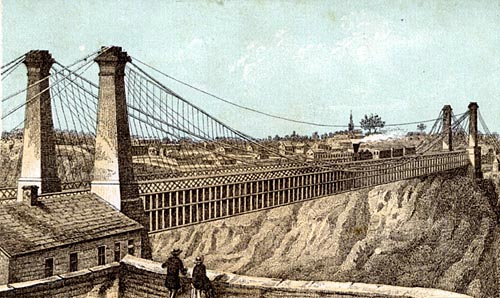
The history of the suspension bridge and its use for railroads can almost completely be traced to one span - the Niagara suspension bridge. Like all bridges of the type, two tall towers support a thick steel cable that sags down on either side between them while the far ends of the cable terminate into heavy anchorages that resist the pull or tension exerted on the cables from the weight of the bridge deck. The deck of the bridge hangs from a series of thin, vertical cables called stringers that are connected to the two main cables. The tall towers and swooping lines of a large scale suspension bridge can make them the most breathtaking and spectacular of all bridge types.
Designed by John Augustus Roebling, who became famous for designing the Brooklyn bridge 30years later, the New York to Canada structure at Niagara Falls would become the only major North American suspension bridge ever built to carry full size trains with heavy locomotives. Its success nearly led to the building of a similar bridge across the Kentucky River before it was decided to build a steel cantilever bridge - America’s first - that would be more suited for heavy trains. Ultimately, early suspension bridges, even with the addition of stiffening trusses, were too susceptible to distortions and unwanted movements that could eventually damage the structure. With increased traffic and the demand for a double-track across the gorge, the 821 foot long (250 meter) suspension bridge was finally replaced in 1897 with an arch that was built underneath and around the Roebling span.
Roebling’s two other great 1800s suspension bridge crossings at Cincinnati, Ohio and Brooklyn, New York would also have rail lines but only for lighter transit trains and trolleys. In the early 1900s, transit lines would also be built on New York City’s two other big suspension bridge projects, the Williamsburg and Manhattan bridges. After these, the last two North American suspension bridges to ever have a light rail line would be Philadelphia’s Benjamin Franklin bridge in 1926 and San Francisco’s Oakland Bay Bridge in 1936. The two rail lines on the lower deck of the Bay Bridge were converted to road use in 1963, leaving New York and Philadelphia as the last two cities in North America to have rail line suspension bridges.
In recent years, the most interesting road and rail suspension bridges have been opening overseas. The most prominent of these is the Seto-Ohashi rail line that skips across several islands and bridges on the middle crossing of the massive Honshu-Shikoku bridge project that opened in 1988 in Japan. Of the six major spans, three are suspension including the Kita and Minami bridges which are back to back, sharing a common anchorage in the same way as the suspension bridges of the San Francisco-Oakland Bay bridge.
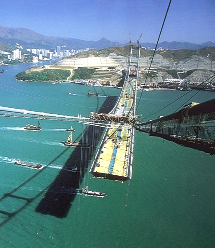
In 1997 the Tsing Ma suspension bridge opened in Hong Kong, China and is currently the longest span railway bridge in the world with a central span of 4,518 feet (1,377 meters). It carries 2 MTR transit lines on the lower level as well as 6 lanes of roadway on the upper level.
Cable Stayed Creations
The relation between railroads and cable stayed bridges has been minimal given that the golden age of railroading peaked in the early 1900s, nearly half a century before the first modern cable stayed bridges arrived in the 1950s. The basic cable stayed bridge form consists of two tall towers with a series of one or more cables that radiate down to directly support the deck. Unlike a suspension bridge where the weight of the deck is partially transferred to massive ground anchorages, a cable stayed bridge is more like a cantilever bridge where the weight of the spans on either side of the tower balance each other out. Since cable stayed bridges are inherently stiff, the decks can be made thinner and hence more attractive than those of other bridge types.
Even though much of the current cable stayed bridge craze comes from their economy and ease of construction, the variety of design options has also played a large factor in their popularity. With little exception, suspension bridges generally look the same while cable stayed bridges have towers that can be shaped like a diamond or the letter A, or an H, or an inverted Y or even a simple I while the “fan” arrangement of cables can be radial, parallel or somewhere in-between with even further variations coming from the use of one or two cable planes. If the overall length of a cable stayed bridge will be short, only a single tower may be required while three or more can be be used for longer crossings. With some colorful lighting, the bridge can become a unique, dramatic signature on the skyline of a city.
The earliest use of a cable stayed bridge for trains can almost exclusively be traced to the French engineer Gisclard who built several sizeable spans including one of 512 feet (156 meters) for the famous 1909 built Cassagne bridge on a narrow gauge railway in the mountainous Eastern Pyrenees region of France. Gisclard’s bridges were unique in that the angled stays do not terminate in the deck but continue to travel horizontally a few feet above the deck until they reach a ground anchorage at the far end of the bridge. Another French engineer, G. Leinekugel le Cocq, built the Lezardrieux rail bridge over the Trieux river in Brittany, France in 1924 with a design similar to Gisclard’s but with the stays terminating at the deck like a modern cable stayed bridge.
Despite being more rigid than a suspension bridge, cable stayed bridges are still not well suited to the heavy loads that a normal train can exert on them. One option that preserves much of the look of a cable stayed bridge with the necessary strength is the extra dosed bridge. Developed in Japan in the 1990s, extra dosed bridges are a cross between a concrete beam bridge and a cable stayed bridge. Unlike a cable stayed bridge where the stays are generally spaced evenly across the entire deck from tower to tower, the center third of an extra dosed bridge is usually devoid of cables as is the immediate area on either side of the main towers where there is always an open “window”. By relying much more on the strength of the thicker, prestressed concrete beam span below the roadway, extra dosed bridges can have much shorter towers with fewer cables. In some ways extra dosed bridges are not suitable for long spans and they have been built primarily as a prettier alternative to the dull look of a pure beam bridge. Their use has been almost exclusively limited to Japan where more than a hundred have been built to date for both road and rail use. The first North American structure of its type will be the Pearl Harbor Memorial bridge, currently under construction in New Haven, Connecticut and due to open in 2016.

