Difference between revisions of "Aizhai Bridge/Page 2"
| Line 140: | Line 140: | ||
[[File:AizhaiBogie4.jpg|750px|center]] | [[File:AizhaiBogie4.jpg|750px|center]] | ||
| + | |||
| + | |||
| + | [[File:AizhaiWheelBogieView2.jpg|750px|center]] | ||
| + | In the above view you can see the process where the suspended truss sections roll along horizontal cables connected to the vertical suspender cables. The large green beam is a crane whose only function is to raise each truss section several meters into place. The yellow wheel bogies travel back to the cliff side staging area to carry another truss section and the process repeats until the truss is completed. This complex and experimental system was used for the first time ever on Aizhai. | ||
| Line 146: | Line 150: | ||
[[File:AizhaiDeckMove3.jpg|750px|center]] | [[File:AizhaiDeckMove3.jpg|750px|center]] | ||
| − | + | A diagrams shows how the truss is rolled over cables before eventually being raised into place by the green crane that is not shown here. The design may also have been modified as the wheel bogies roll over the blocks at the bottom of each suspender yet the diagram shows the truss below these blocks as well as being pulled along by cables attached to the truss. | |
| − | |||
| − | |||
| − | |||
| Line 160: | Line 161: | ||
[[File:AizhaiDeckMove4.jpg|750px|center]] | [[File:AizhaiDeckMove4.jpg|750px|center]] | ||
| + | A diagram shows how the truss is raised into position by the crane that rolls along on the 2 main suspension cables. This crane is only used to raise the truss sections and not move them. | ||
Revision as of 22:54, 5 November 2011
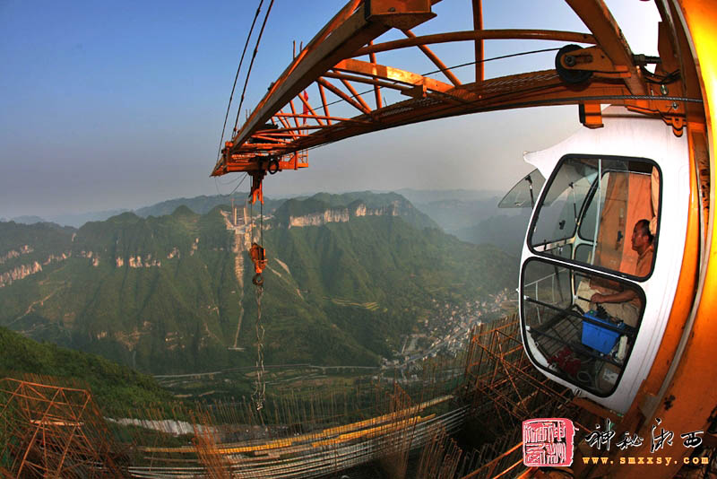
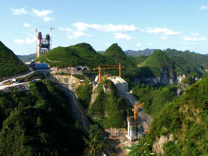
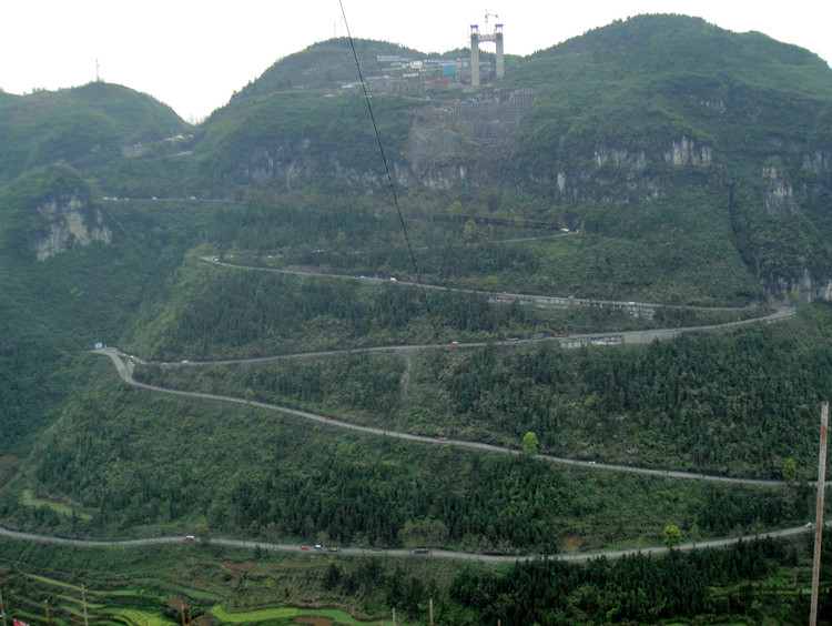
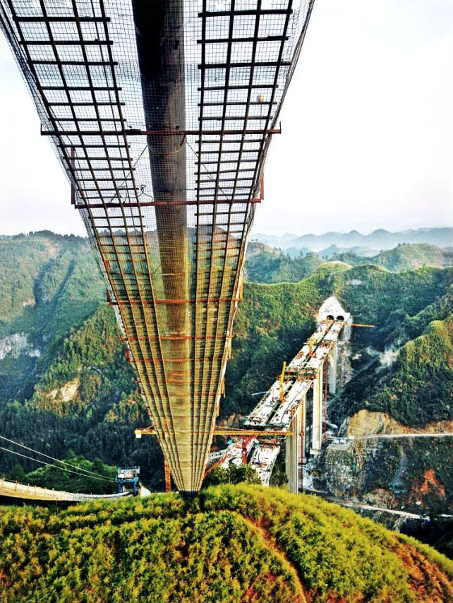
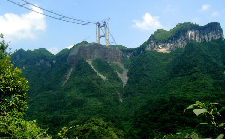
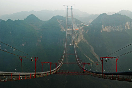
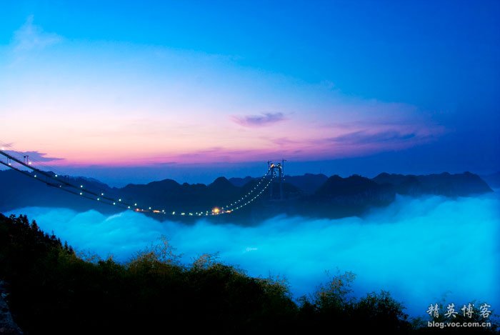
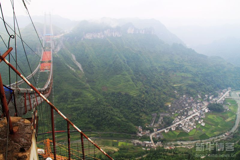
Looking like a scene from the movie Avatar, the deep canyon dwarfs the north tower in the upper left.
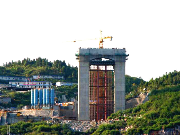
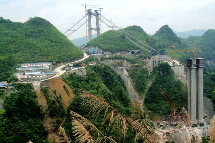
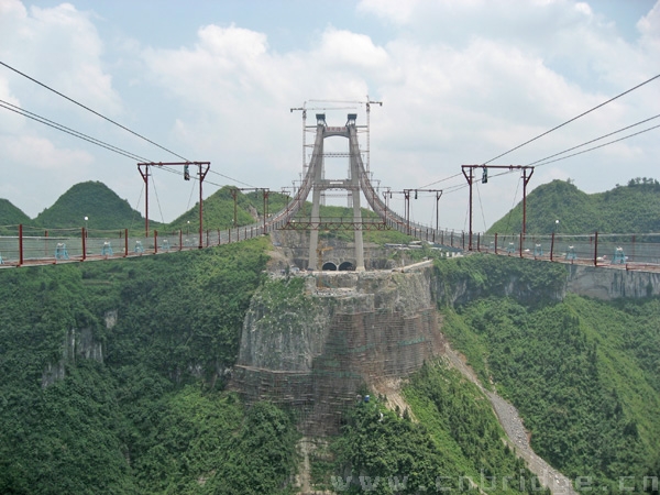
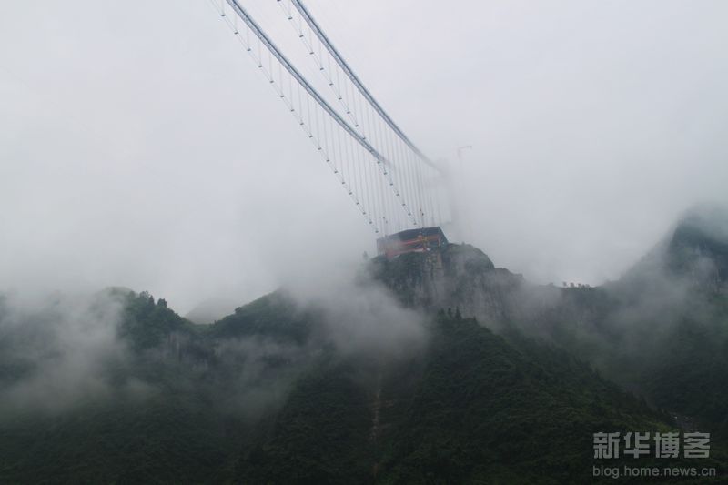
The view from the north side with the short tower shows the taller south tower halfway complete on the far side of the canyon. Image by www.smxxsy.com
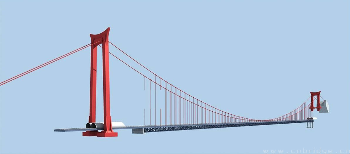
An early Aizhai computer rendering. In the final design, the taller tower has a horizontal cross brace with more ordinary antenna-like tower tops. The tunnel was also changed and does not extend under the taller tower.
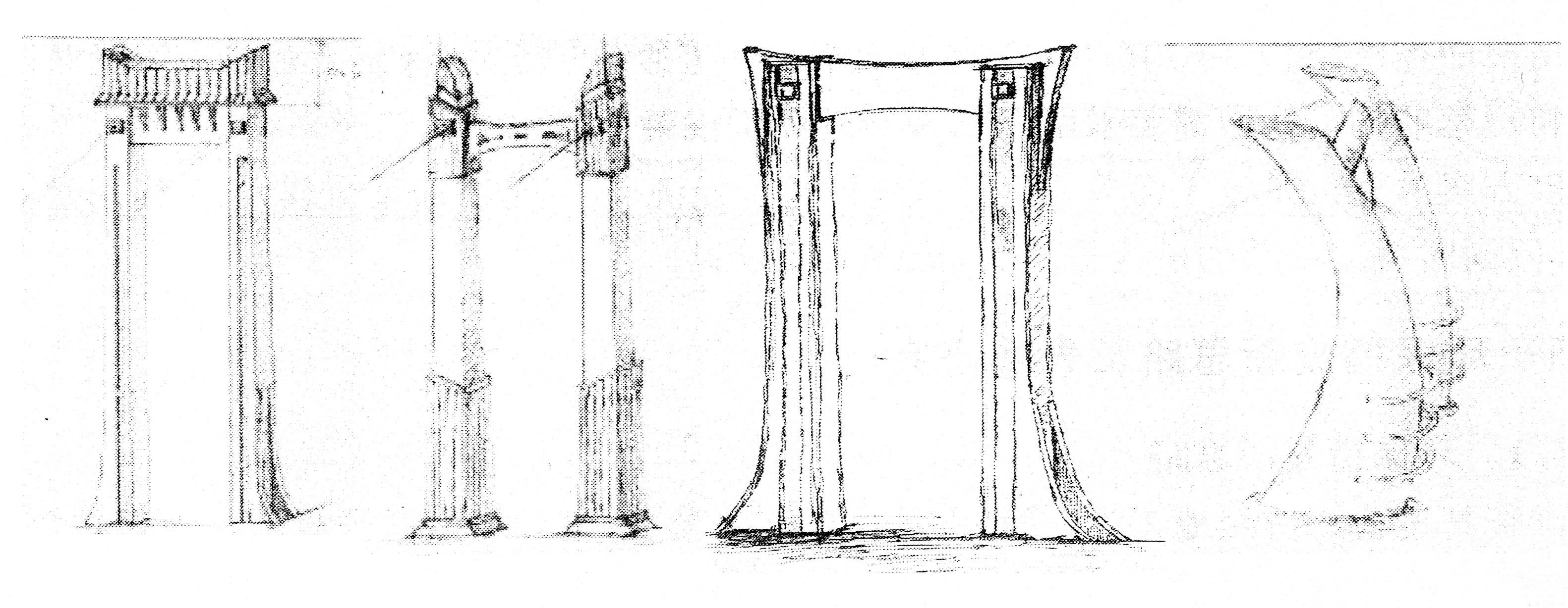
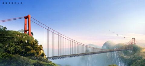
Several Aizhai bridge tower designs.
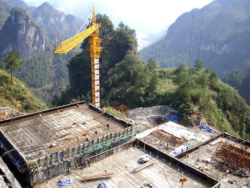
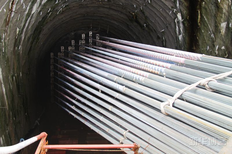
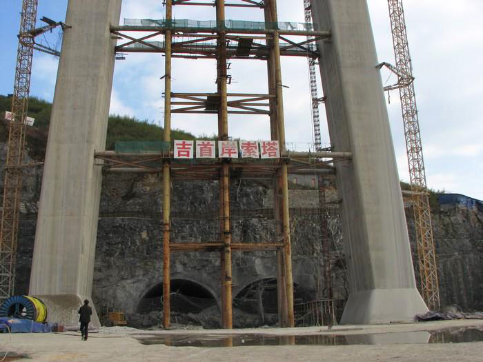
One of the cable anchorages located on the back side of the mountain range.
The wire bundles are connected to a deep underground concrete wall.
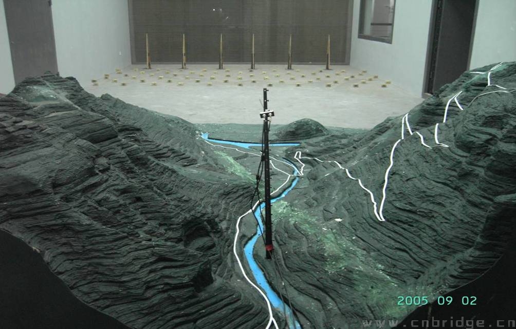
Aizhai valley wind test model.
Note how close the foliage is to the back span cables.
The tunnel entrances beneath the tall tower.
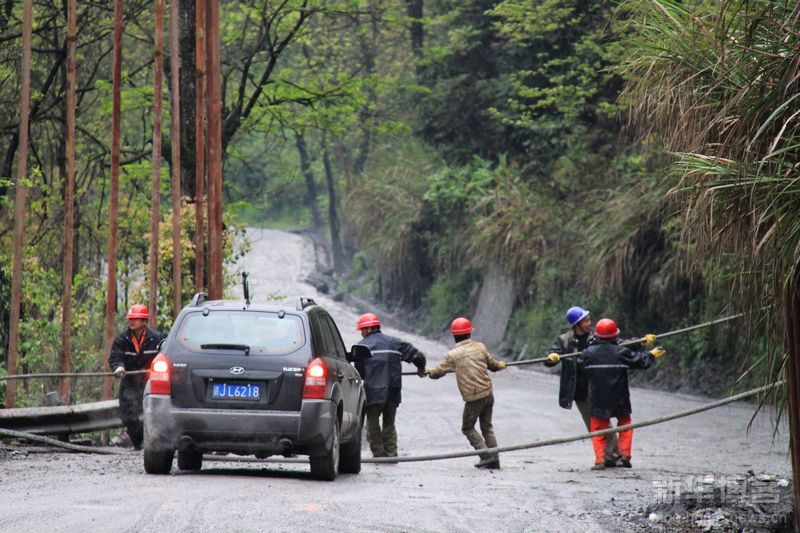
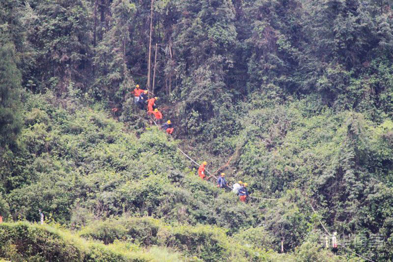
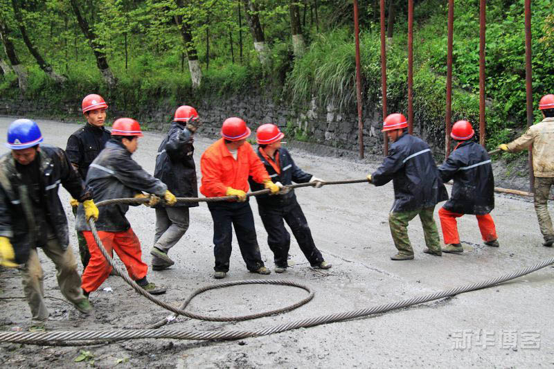
One of the cables sagged down into the gorge during the early process of setting up the catwalks. The Chinese workers quickly freed up the cable and hoisted it out of the valley.
You can view a video here of the preparation to use a small blimp to take the first pilot line across. http://bbs.rednet.cn/thread-22618784-1-1.html
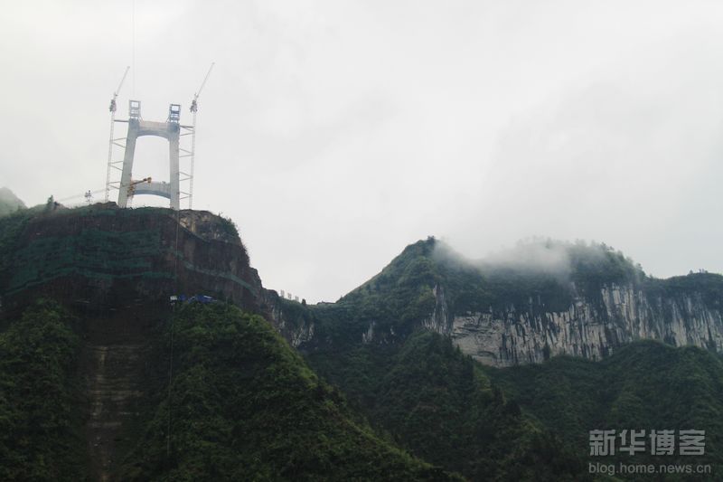
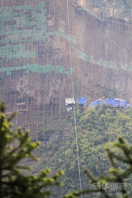
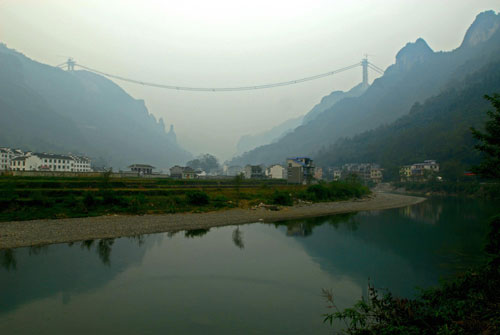
The hanging cable reveals just how high up the rock face scaffolding is below the south tower.
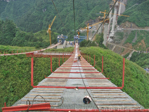
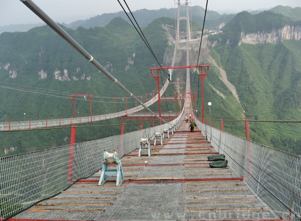
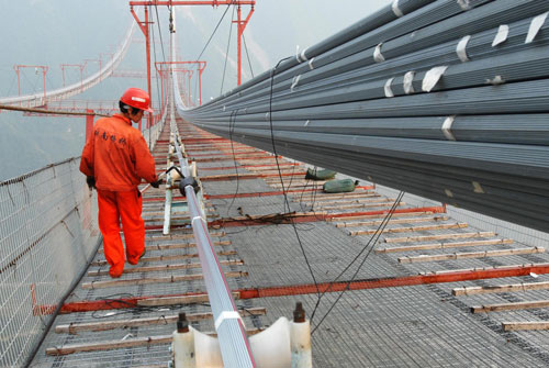
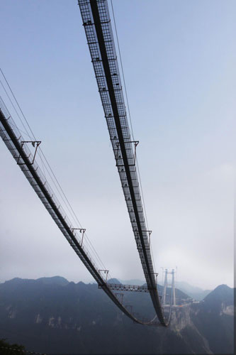
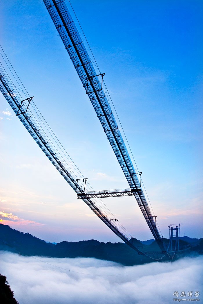
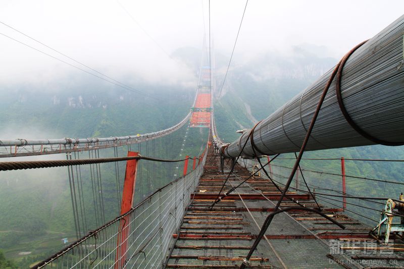
The catwalks were in place by mid-2010.
The wires are always grouped into hexagon shaped bundles that fit together within the larger main cable like the pieces to a puzzle.
The main cables were completed in the fall of 2010.
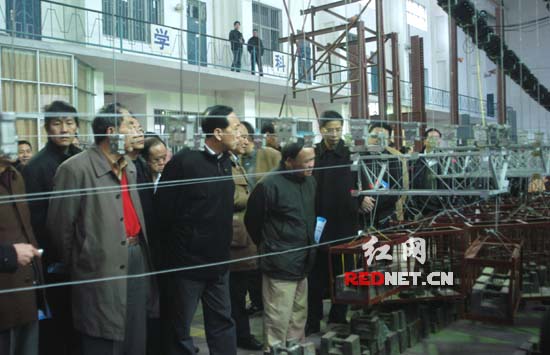
A large model was created to show the unique process where the truss sections will be pulled and rolled along hanging cables with wheel bogies attached to them.
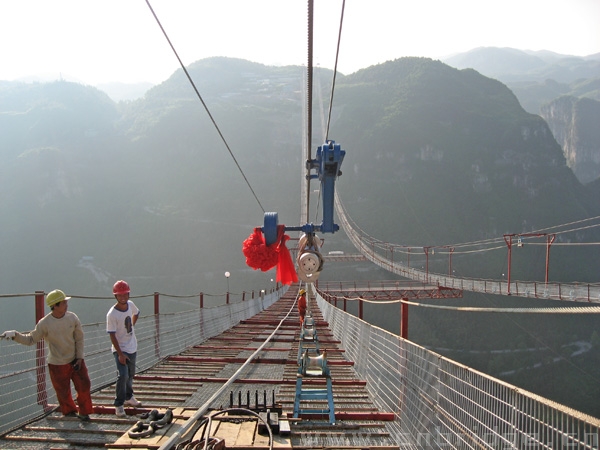
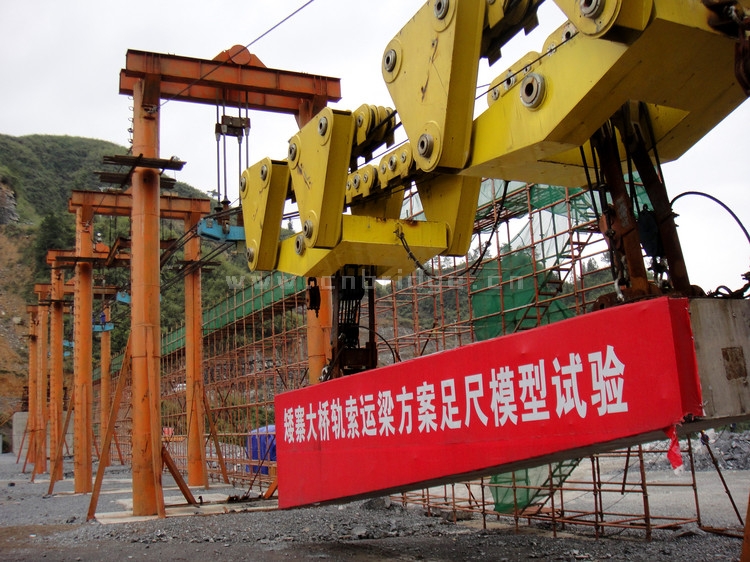
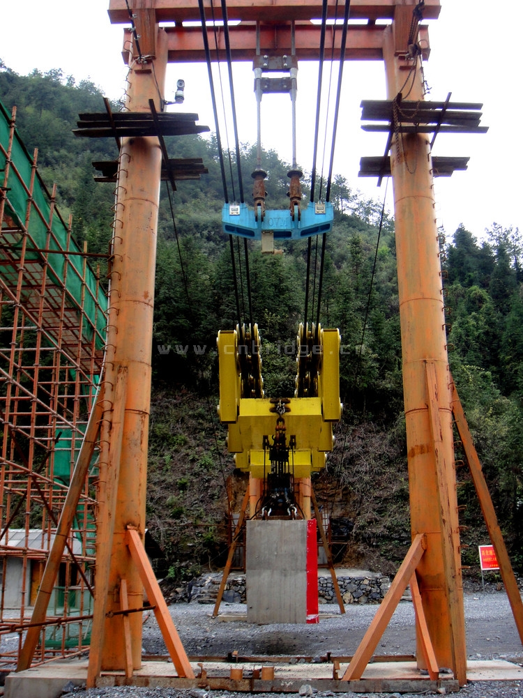
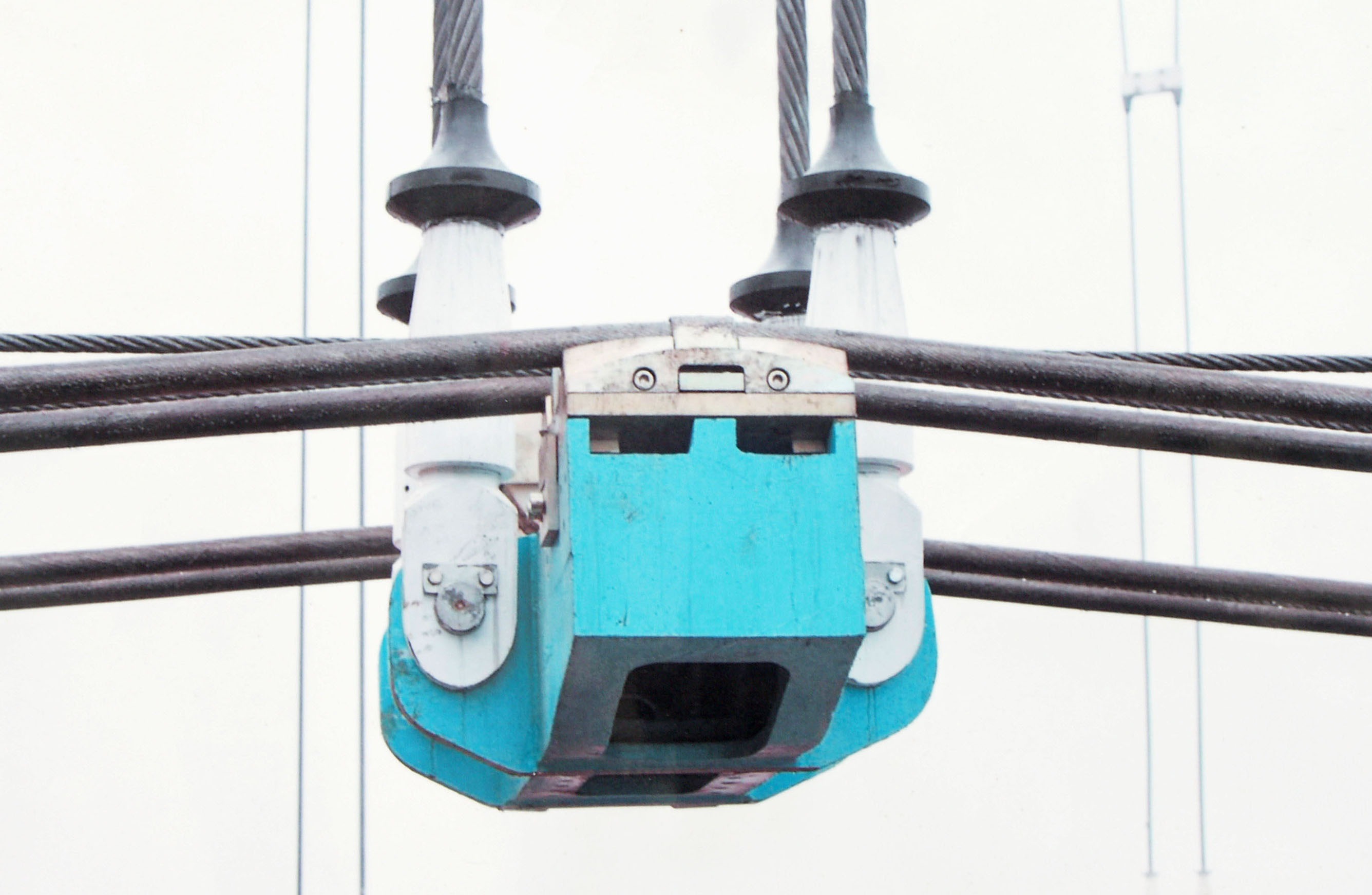
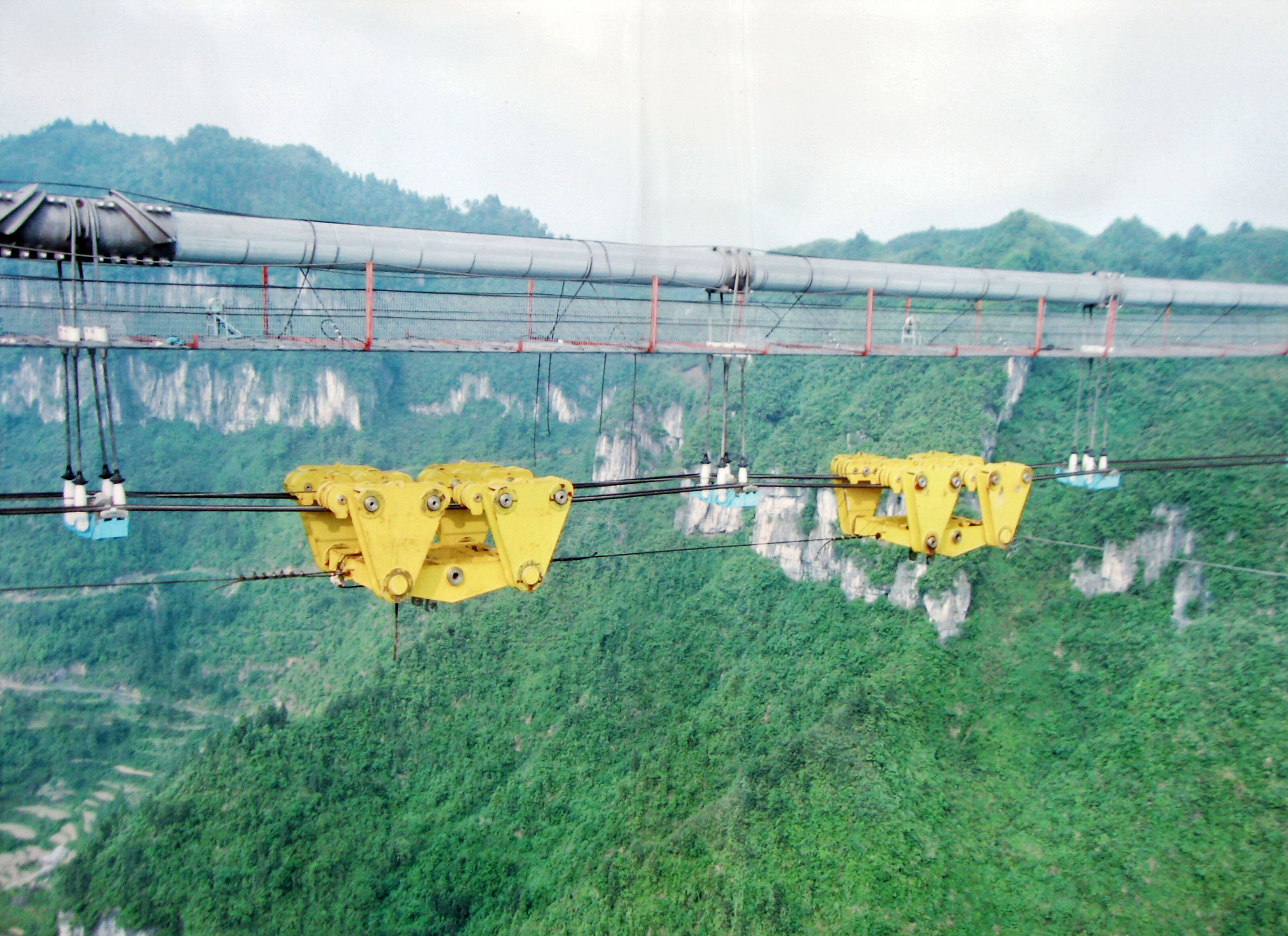
One of the massive bogies especially designed to pull the suspended truss sections out over the gorge.
A test section was set up for the traveling bogies. The temporary supports simulate the stringer intervals where the bogies will travel on cables that are connected to the ends of the stringers.
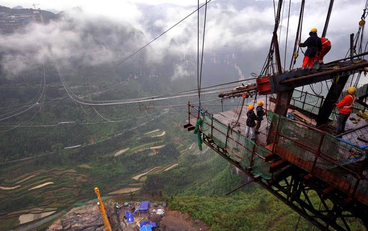
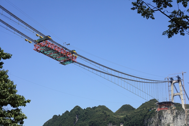
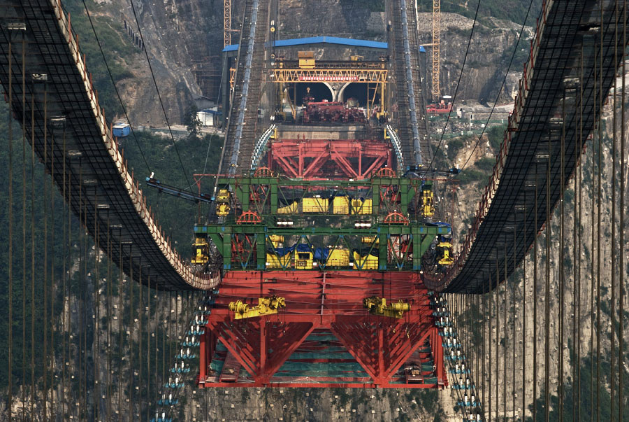
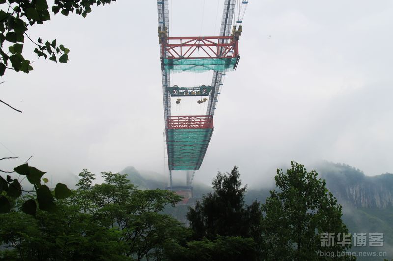
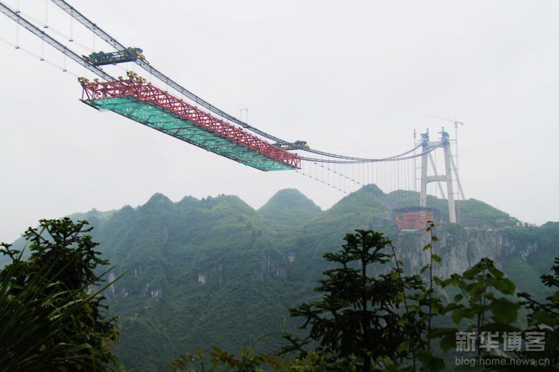
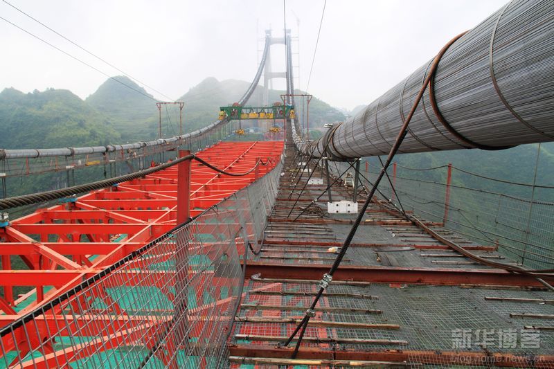
In the above view you can see the process where the suspended truss sections roll along horizontal cables connected to the vertical suspender cables. The large green beam is a crane whose only function is to raise each truss section several meters into place. The yellow wheel bogies travel back to the cliff side staging area to carry another truss section and the process repeats until the truss is completed. This complex and experimental system was used for the first time ever on Aizhai.
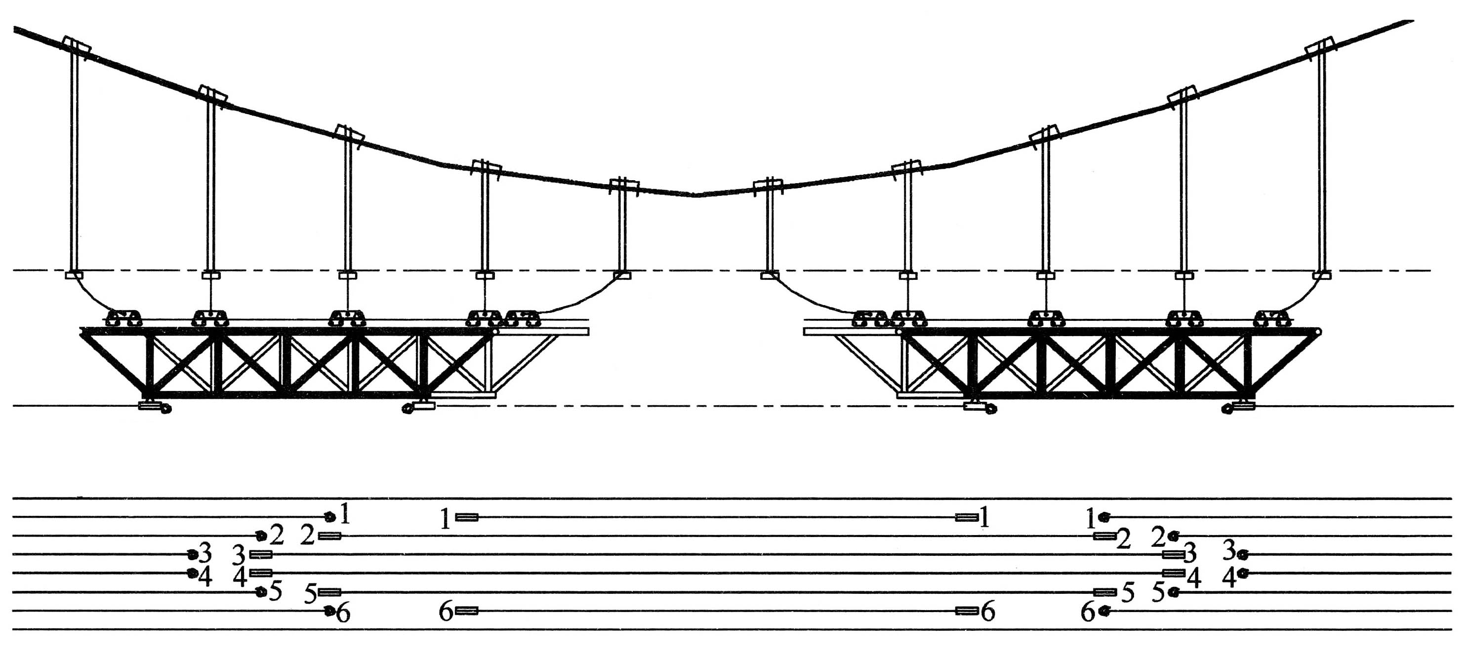
A diagrams shows how the truss is rolled over cables before eventually being raised into place by the green crane that is not shown here. The design may also have been modified as the wheel bogies roll over the blocks at the bottom of each suspender yet the diagram shows the truss below these blocks as well as being pulled along by cables attached to the truss.
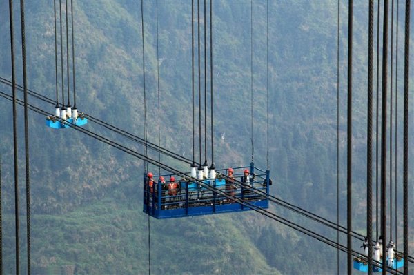
Aizhai Bogies travel back to the staging area to pick up another truss section.
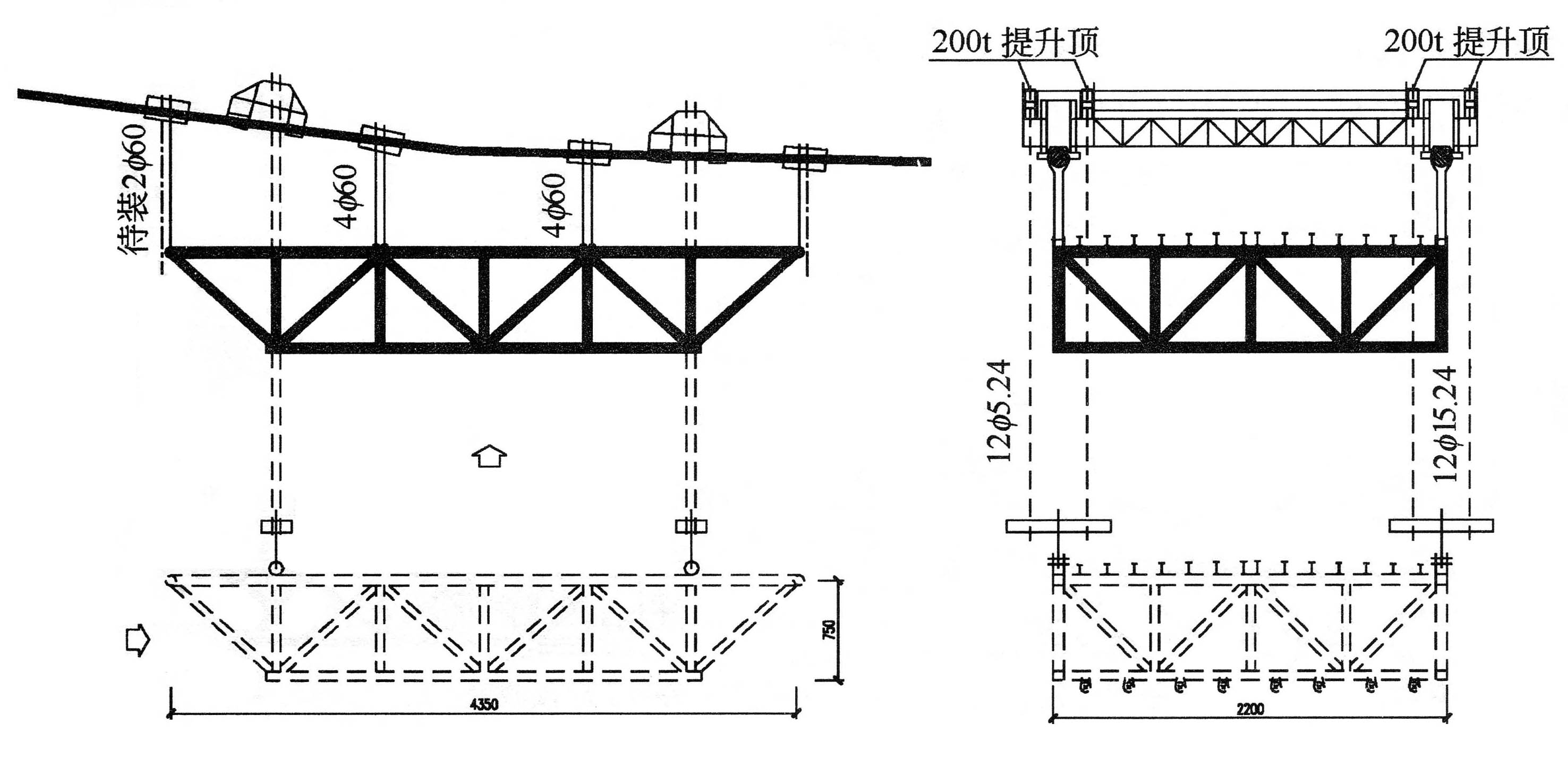
A diagram shows how the truss is raised into position by the crane that rolls along on the 2 main suspension cables. This crane is only used to raise the truss sections and not move them.
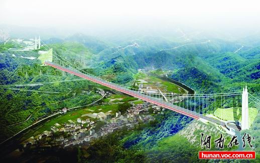
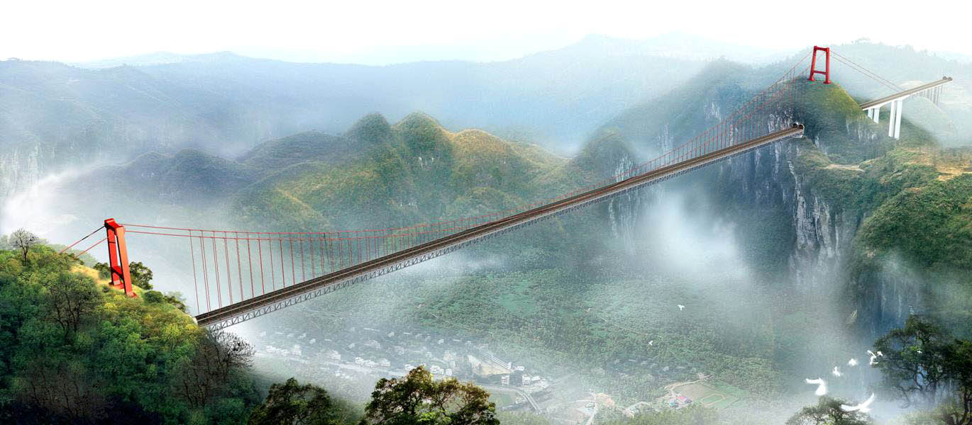
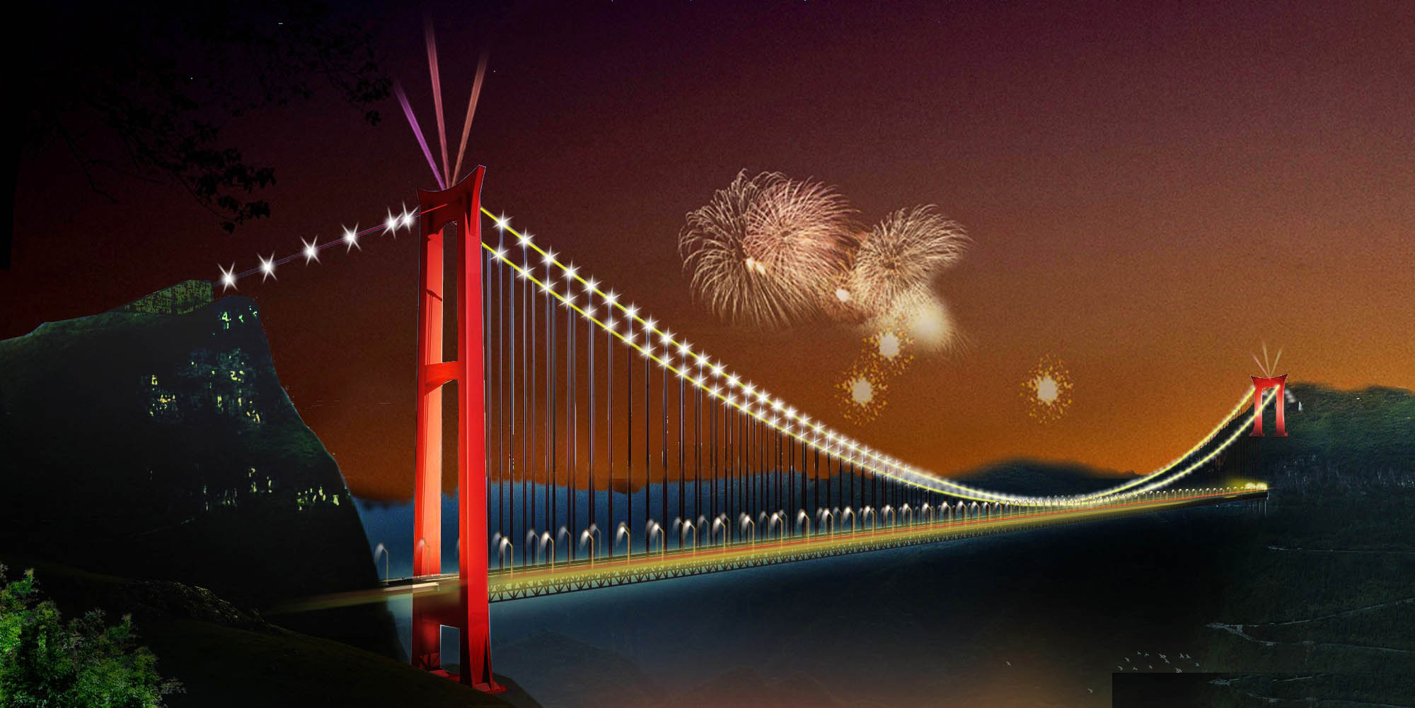
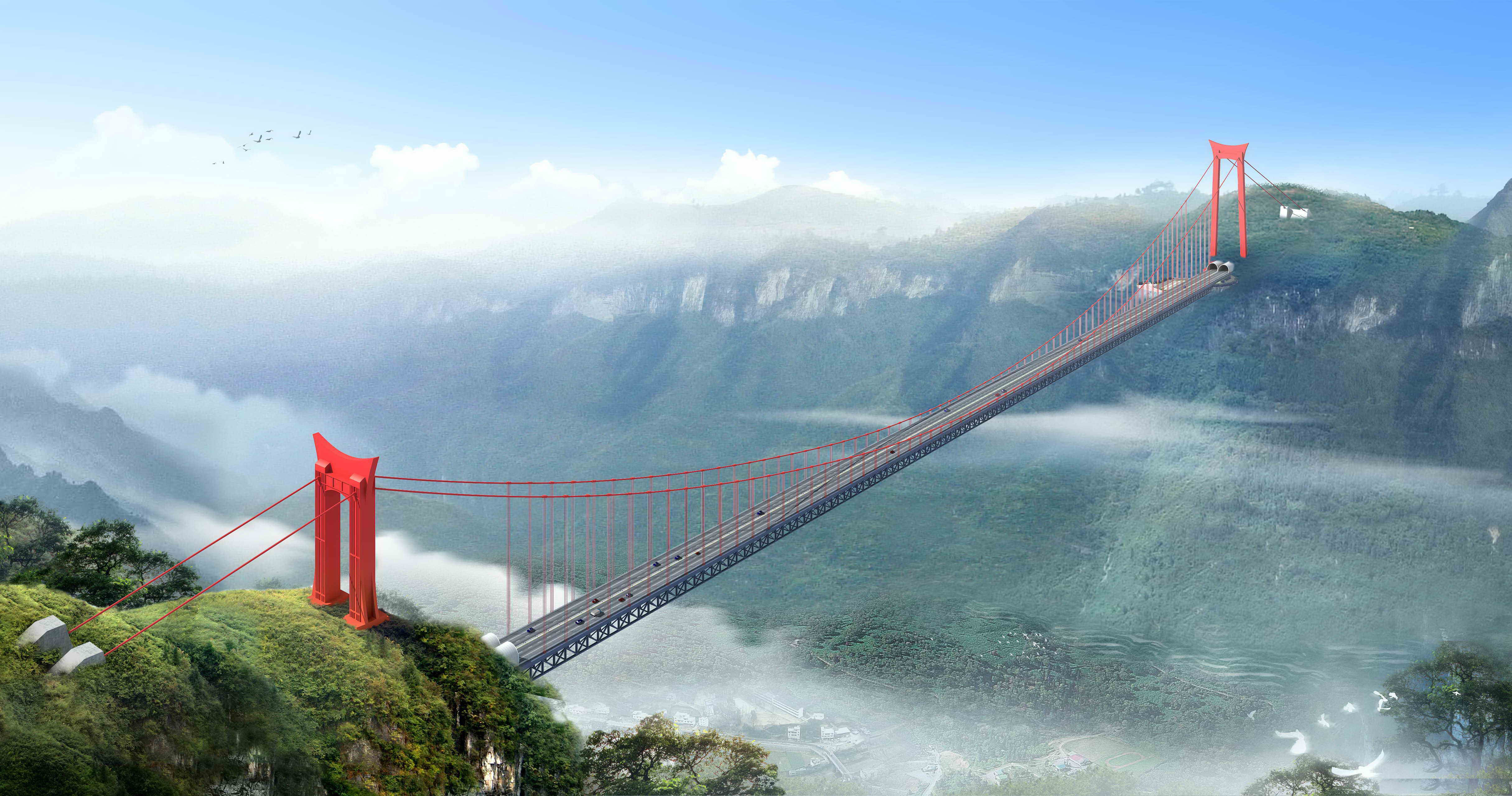
The most recent rendering showing the final design with pointed ornamentation on the tower tops.
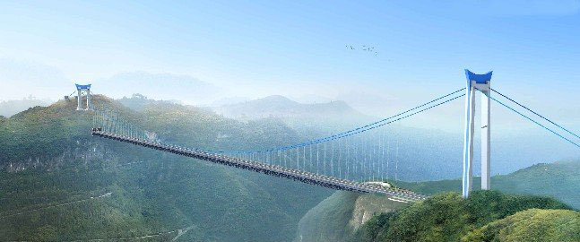
An earlier drawing showing a blue pin stripe paint scheme.
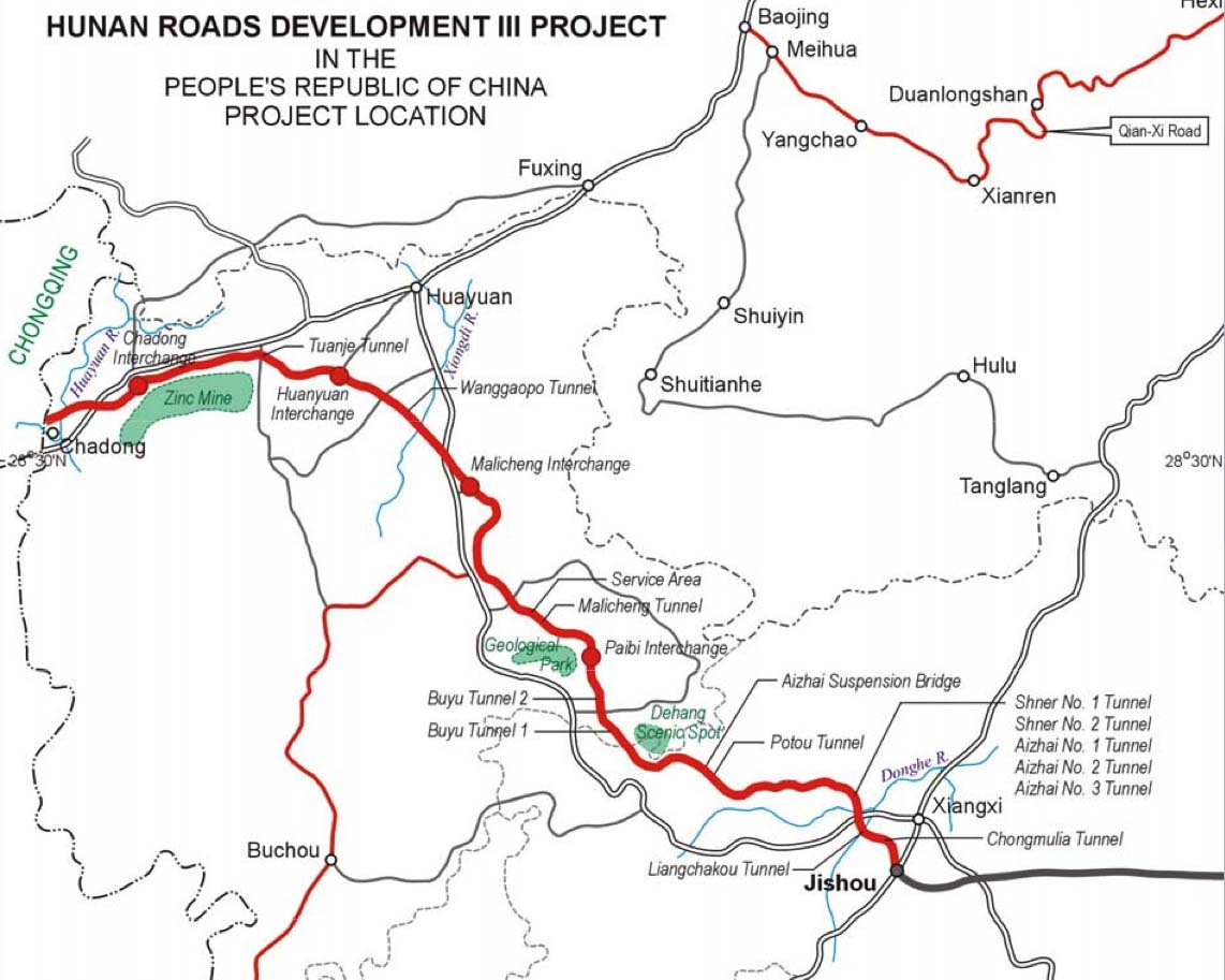
Map of the new highway northwest of Jishou.
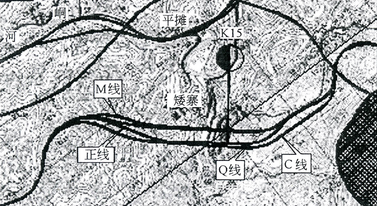
A map showing the various Aizhai bridge routes and proposals that were studied.
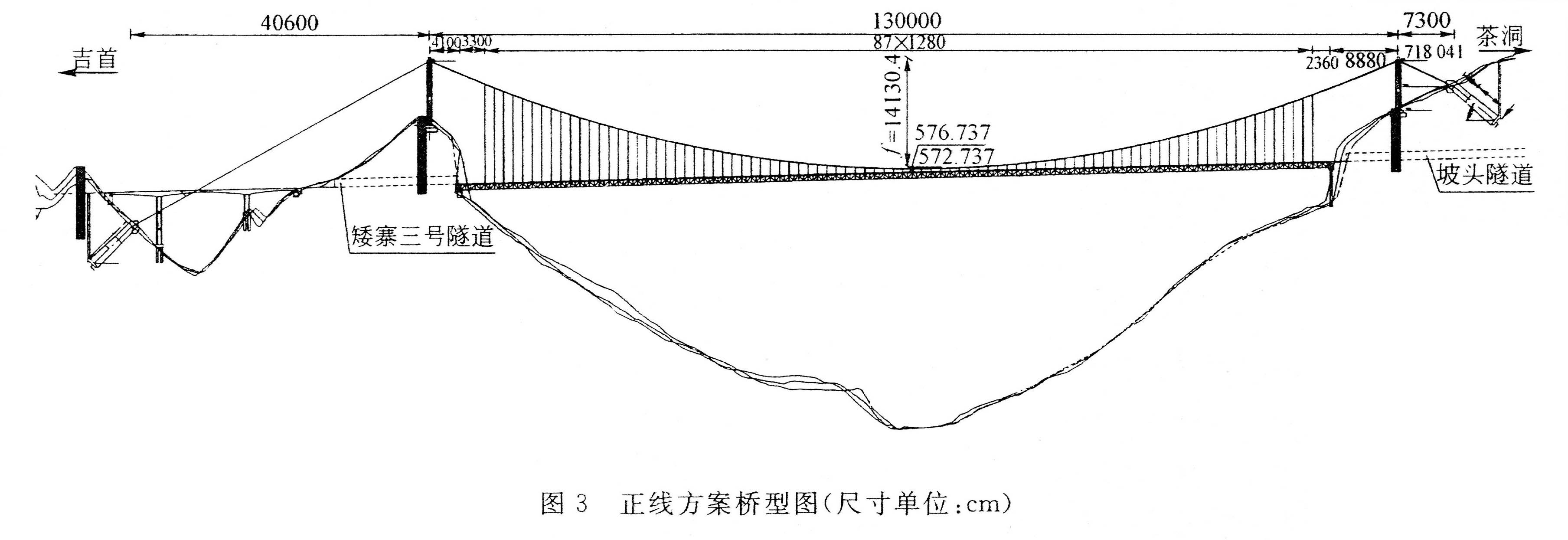
Aizhai bridge proposal 1 would have required an unusually long main span of 1,300 meters and a lengthy side span but both towers would have been short.
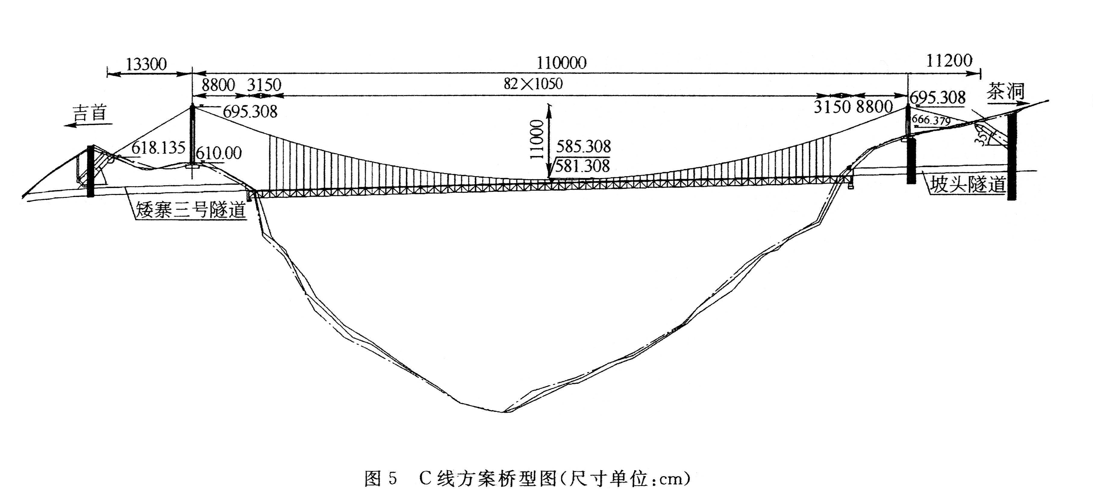
Proposal C would have had a main span of just 1,100 meters and is similar to the final design.
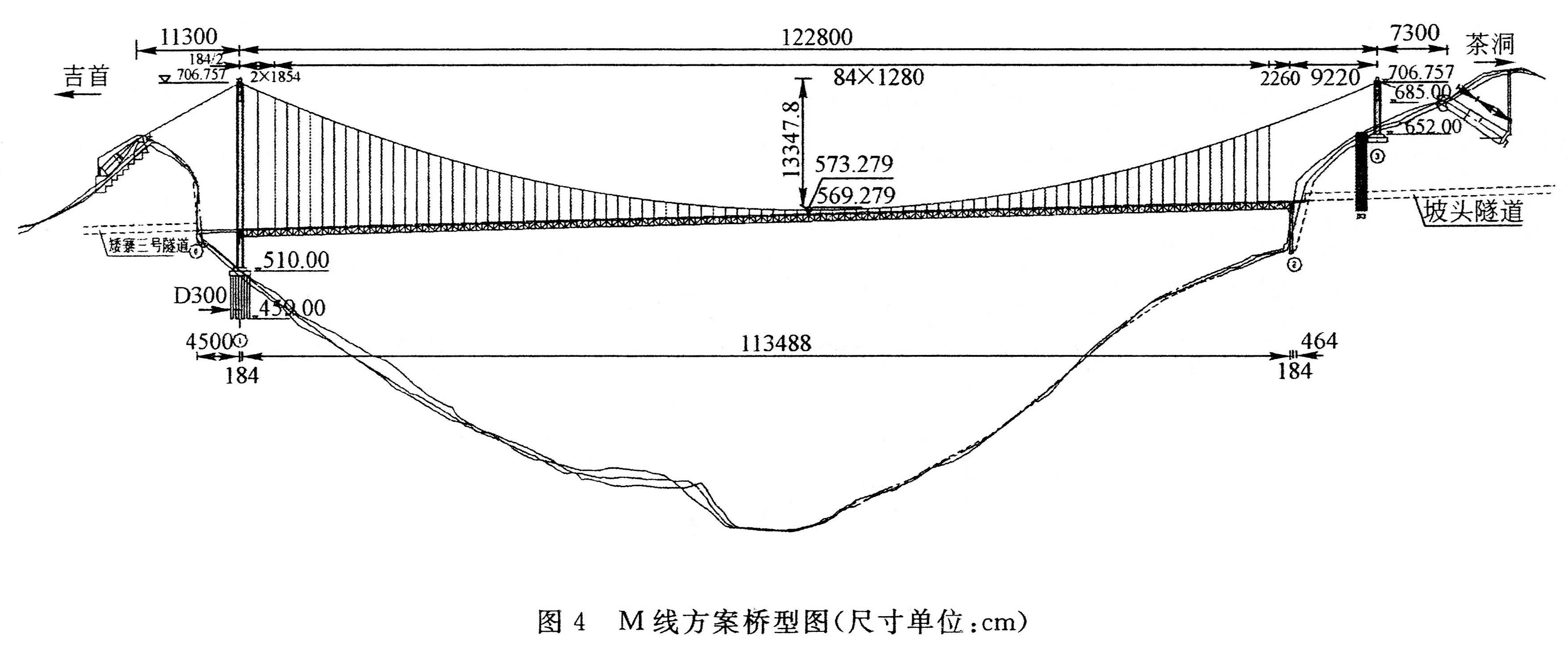
Proposal M would have had a main span of 1,228 meters but required a tower almost 200 meters high as well as an anchorage resting on a steep mountain slope.
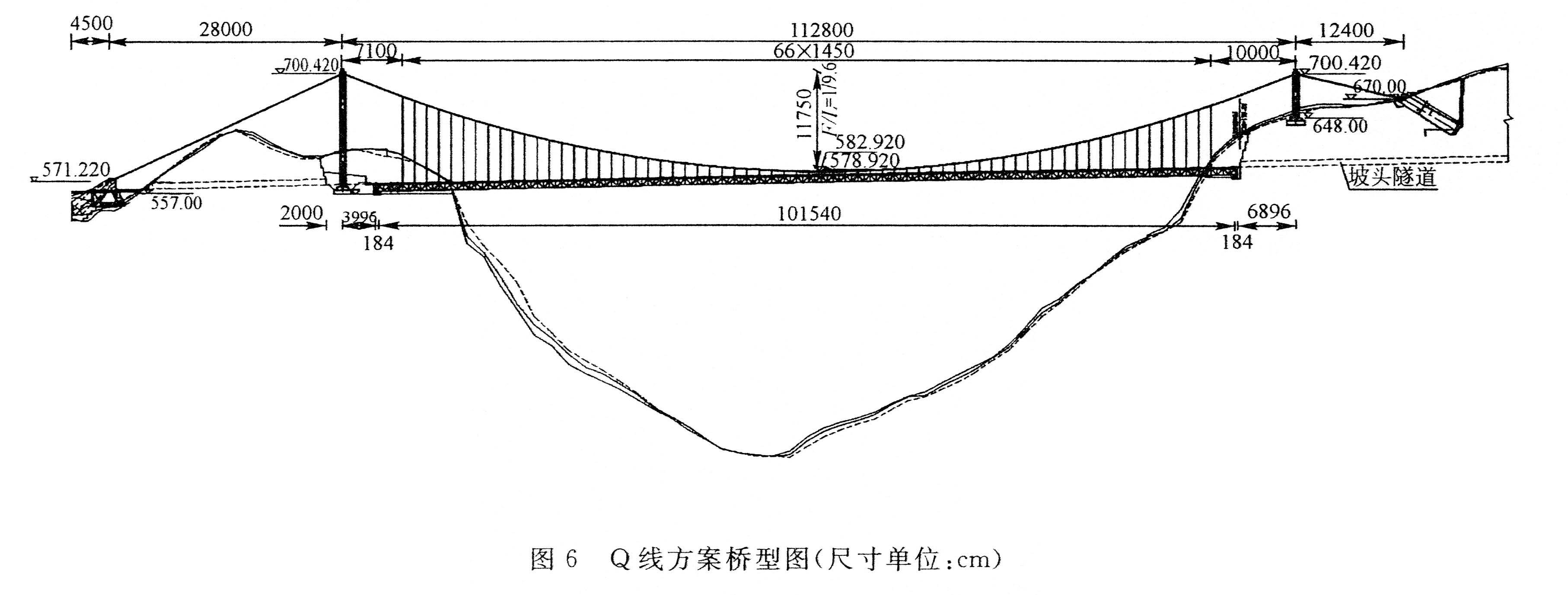
Proposal Q is very similar to the final design but with a slightly shorter main span of 1,128 meters.
